Understanding the Warner Electric Clutch Brake in Auxiliary Drivetrains
When exploring the world of heavy-duty automotive auxiliary drives, Power Take-Off (PTO) systems, and industrial manual transmission retrofits, you will frequently encounter electromagnetic engagement components. Among the most respected names in this space is the Warner Electric clutch brake. Unlike a standard automotive friction clutch that relies on hydraulic pressure and a pedal mechanism, an electromagnetic clutch-brake utilizes magnetic fields to engage a drive and spring-loaded friction to stop it the millisecond power is cut.
For beginners and seasoned mechanics alike, diagnosing engagement and disengagement issues on these units can seem intimidating. However, the underlying physics are straightforward. Whether you are maintaining a PTO drive on a commercial work truck, an auxiliary compressor drive, or a specialized drivetrain adaptation, understanding why your Warner Electric unit fails to engage—or worse, fails to disengage and brake—is critical for both operational efficiency and safety.
In this 2026 beginner-friendly guide, we will break down the anatomy of these components, identify the most common failure modes, and provide a concrete, step-by-step diagnostic framework to get your drivetrain back online.
How an Electromagnetic Clutch-Brake Actually Works
Before turning a wrench, it is vital to understand the dual nature of a 'clutch-brake' assembly. It performs two distinct functions depending on its electrical state:
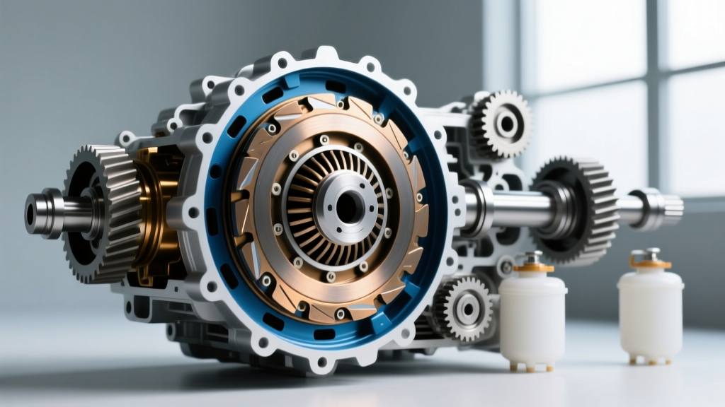
- Engagement (Power ON): When DC voltage (typically 12V or 24V) is applied to the electromagnetic coil, it generates a magnetic field. This field pulls the steel armature across a tiny air gap, clamping it against the rotating rotor. Friction locks the components together, transferring torque from the transmission output to the auxiliary drive.
- Disengagement & Braking (Power OFF): When the electrical current is severed, the magnetic field collapses instantly. Heavy-duty return springs push the armature away from the rotor, breaking the drive connection. Simultaneously, those same springs force the armature against a stationary brake friction surface, halting the auxiliary shaft's rotation in milliseconds to prevent dangerous freewheeling.
Because these units operate in harsh environments near transmission output seals and road debris, they are highly susceptible to contamination, thermal stress, and electrical degradation. According to engineering documentation from Altra Industrial Motion, the parent company of Warner Electric, improper air gap maintenance and voltage drops are the leading causes of premature failure in PTO clutch systems.
Top Symptoms of Engagement & Disengagement Failure
Identifying the exact symptom is the first step in our diagnostic framework. Pay close attention to how the drivetrain behaves when you toggle the PTO or auxiliary drive switch.
1. Complete Failure to Engage (No 'Click')
If you flip the switch and hear nothing, and the auxiliary shaft does not turn, the magnetic field is not being generated. This is almost always an electrical issue: a blown fuse, a broken wire, a failed relay, or an internally open coil. Occasionally, if the air gap has worn excessively wide, the magnetic field simply cannot bridge the distance to pull the armature.
2. Slipping Under Load
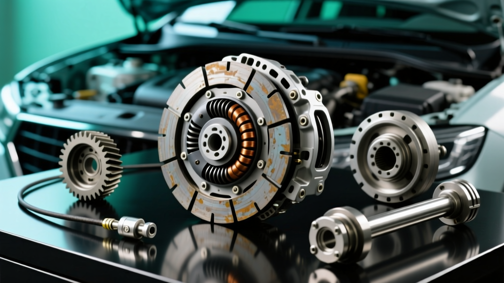
You hear a loud 'clack' indicating the armature has engaged, but the auxiliary drive struggles to spin under load, or you smell burning friction material. This indicates that the clamping force is insufficient. Causes include oil contamination leaking from the adjacent transmission output shaft seal (a common issue on adapted manual gearboxes like the Eaton Fuller or ZF manual transmissions), worn friction facings, or low system voltage reducing the magnetic pull.
3. Failure to Disengage or Brake (Dragging)
This is the most dangerous symptom. When power is cut, the auxiliary shaft continues to spin, or the brake fails to hold it. This can be caused by residual magnetism in the rotor (often due to overheating or using the wrong DC voltage type), mechanical binding in the anti-rotation straps, or warped armatures that physically wedge against the rotor even without magnetic force.
The 3-Step Diagnostic Framework
Grab your digital multimeter (DMM) and a set of feeler gauges. Follow these three steps to isolate the root cause of your Warner Electric clutch brake issues.
Step 1: The Voltage Drop Test (Under Load)
A common beginner mistake is testing the voltage at the connector with the clutch unplugged. An open circuit will show a perfect 12.6V, but the moment the coil draws amperage, a corroded wire will cause the voltage to plummet.
The Fix: Back-probe the connector while the clutch is plugged in and the switch is engaged. You must measure at least 90% of the nominal system voltage (e.g., >10.8V on a 12V system) under load. If the voltage drops below this threshold, the magnetic field weakens, leading to slipping and excessive heat generation in the coil.
Step 2: Measuring and Adjusting the Air Gap
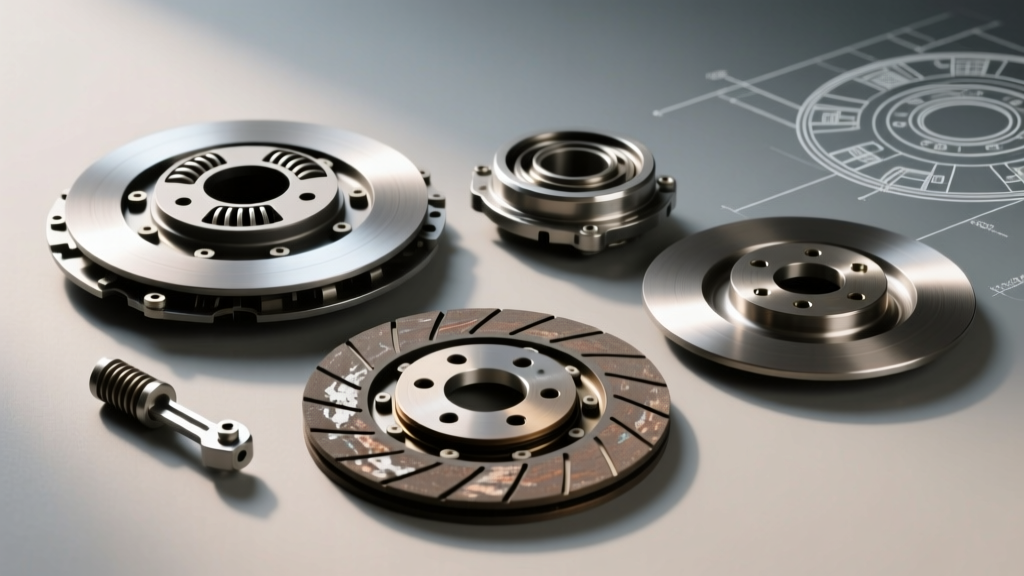
The air gap is the microscopic distance between the rotor and the armature when the unit is disengaged. As the friction surfaces wear down over thousands of engagement cycles, this gap widens. Once the gap exceeds the magnetic field's effective range, the clutch will fail to engage.
The Fix: Use a feeler gauge to measure the gap through the inspection slots or by removing the shroud. For most standard Warner Electric 5000-series PTO clutches, the target air gap is between 0.015 and 0.025 inches. If your measurement reads 0.040 inches or higher, the clutch will not engage. You must remove the armature, take out an adjustment shim, and reassemble to restore the factory specification. Always consult the specific Warner Electric product manual for your exact series, as high-torque models may have different tolerances.
Step 3: Coil Resistance and Grounding Check
If voltage is good and the air gap is within spec, the coil itself may be compromised. Set your multimeter to the Ohms (Ω) setting.
The Fix: Measure the resistance across the coil's two terminals. A healthy 12V DC Warner Electric coil typically reads between 8 and 14 ohms. A 24V coil will read significantly higher (usually between 30 and 50 ohms). If your meter reads 'OL' (Open Line) or infinite resistance, the internal copper windings have snapped, often due to thermal overload. If it reads near zero, the coil has shorted internally. In either case, the coil must be replaced.
Common Warner Electric Models & 2026 Replacement Specs
To help you identify what you are working on, here is a reference table of common Warner Electric clutch-brake series used in automotive auxiliary and industrial PTO applications, complete with 2026 market pricing and critical specifications.
| Model Series | Primary Application | Nominal Voltage | Target Air Gap | Coil Resistance (Approx.) | Est. Replacement Cost (2026) |
|---|---|---|---|---|---|
| Warner 5000 Series | Ag/Commercial Truck PTO | 12V DC | 0.015' - 0.025' | 10 - 14 Ω | $180 - $260 |
| Warner ERD Series | Motorized Aux Drives | 24V DC | 0.010' - 0.020' | 32 - 45 Ω | $340 - $480 |
| Warner CB Series | Industrial Brakes/Drivetrain | 115V AC | 0.008' - 0.015' | Varies (AC Coil) | $450 - $650 |
When to Rebuild vs. Replace the Assembly
One of the most frequent questions we receive at Auto Gear Nexus is whether it is more cost-effective to rebuild a slipping or failing electromagnetic clutch-brake or simply swap the entire unit. The answer depends on the nature of the failure and the availability of friction kits.
If your diagnostics reveal a burnt-out coil or a severely warped armature, complete replacement is usually the most reliable route. The labor involved in pressing out old bearings, extracting broken anti-rotation rivets, and machining warped surfaces often exceeds the cost of a brand-new assembly, which currently ranges from $200 to $500 depending on the torque rating.
However, if the unit is simply slipping due to normal friction wear, and the air gap adjustment shims have been entirely exhausted, purchasing an armature and rotor friction rebuild kit is highly economical. These kits typically cost between $60 and $120. When installing new friction surfaces, it is absolutely critical to clean the surrounding transmission bell housing or PTO port area with a dedicated brake parts cleaner. Even a single drop of synthetic gear oil from the transmission output seal migrating onto the new friction surfaces will ruin the clutch's holding capacity within hours of operation.
Final Thoughts on Drivetrain Safety
Diagnosing a Warner Electric clutch brake does not require advanced engineering degrees, just a methodical approach to electricity, magnetism, and mechanical tolerances. By verifying your voltage under load, strictly adhering to the manufacturer's air gap specifications with a feeler gauge, and testing the coil resistance, you can confidently isolate 95% of all engagement and disengagement issues.
Always remember that in PTO and auxiliary drivetrain applications, a failure to disengage and brake is a severe safety hazard. If your unit exhibits residual magnetism or mechanical binding that you cannot resolve through standard shimming and cleaning, retire the component immediately. For further technical documentation and wiring diagrams, always refer to the official Warner Electric engineering resources to ensure your drivetrain operates safely and efficiently for years to come.