Why Performance Cars Demand Upgraded Hydraulics
When enthusiasts begin upgrading their drivetrains for track-day duty or high-horsepower street use, the clutch assembly is often the first bottleneck. Whether you are swapping a Tremec T56 Magnum into a classic muscle car or upgrading the hydraulic release system on a Porsche 911 GT3, understanding the fluid dynamics at play is critical. Before turning a single wrench, every builder should study a clutch slave cylinder diagram to visualize how hydraulic pressure translates into mechanical clamping force.
Unlike standard passenger vehicles that prioritize soft pedal effort and long service intervals, performance vehicles require immediate engagement, high thermal tolerance, and precise modulation. As of 2026, the aftermarket has largely standardized around modular, high-pressure hydraulic components that allow tuners to mix and match master and slave cylinders to achieve the perfect pedal feel. In this beginner-friendly explainer, we will break down the anatomy of a performance hydraulic system, decode the flow diagrams, and provide the exact specifications you need for your next build.
The Anatomy of a High-Performance Hydraulic System
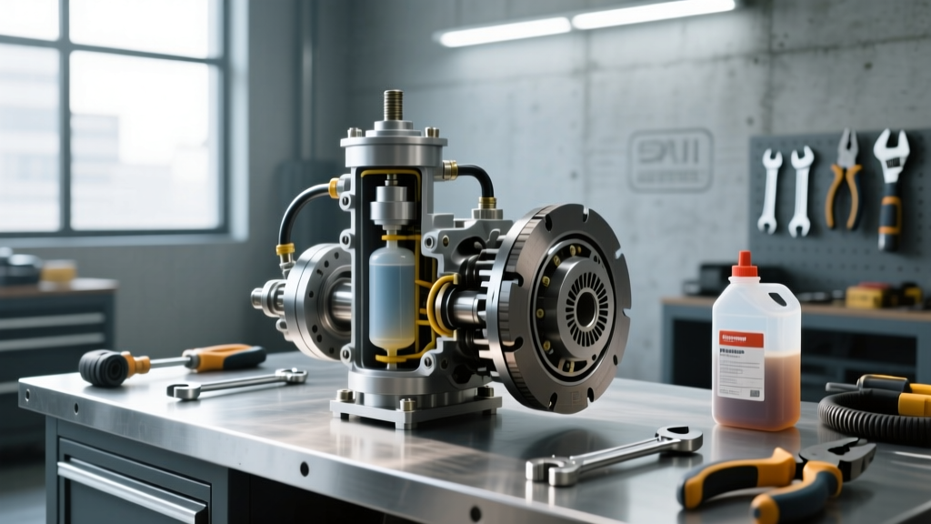
A performance clutch hydraulic system consists of three primary stages: the master cylinder, the transfer line, and the slave cylinder (or hydraulic throw-out bearing). When you depress the clutch pedal, you are acting as the prime mover in a closed-loop hydraulic circuit.
- The Master Cylinder (MC): Mounted at the firewall or pedal box, the MC converts mechanical pedal force into hydraulic pressure. Performance setups typically utilize aluminum-bodied, top-loading cylinders with adjustable pushrods to eliminate dead-play.
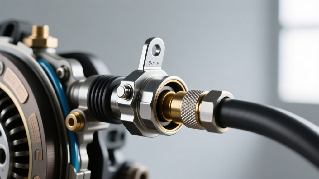
- The Transfer Line: Factory rubber hoses expand under high pressure, leading to a spongy pedal. Performance diagrams replace these with stainless steel braided AN-3 (3/16-inch ID) lines, often routed through the chassis using bulkhead fittings to prevent chafing.
- The Slave Cylinder (SC): The SC receives the pressurized fluid and pushes the clutch fork or directly actuates the pressure plate fingers. In high-end motorsports, this is where the magic happens, and reading a clutch slave cylinder diagram is essential to understanding piston stroke and bore sizing.
Reading Your Clutch Slave Cylinder Diagram
Because we cannot embed an interactive CAD model here, let us mentally walk through a standard performance clutch slave cylinder diagram for a rear-wheel-drive V8 application. The fluid flow follows a strict, unidirectional path governed by Pascal's Law.
Diagram Flow Path: Fluid Reservoir → Master Cylinder Bore → AN-3 Bulkhead Fitting → Braided Stainless Line → Slave Cylinder Inlet Port → Internal Piston Seal → Throw-out Bearing Face → Pressure Plate Diaphragm Fingers.
Notice that the diagram includes a bleeder screw located at the highest physical point of the slave cylinder. Air naturally rises in a hydraulic system. If your slave cylinder is mounted below the master cylinder (common in transaxle layouts like the Porsche G50 or Corvette C5/C6), the diagram will show a remote bleeder hose routed upward to the firewall to ensure trapped air can be purged.
Concentric vs. Remote Slave Cylinders: A Track Comparison
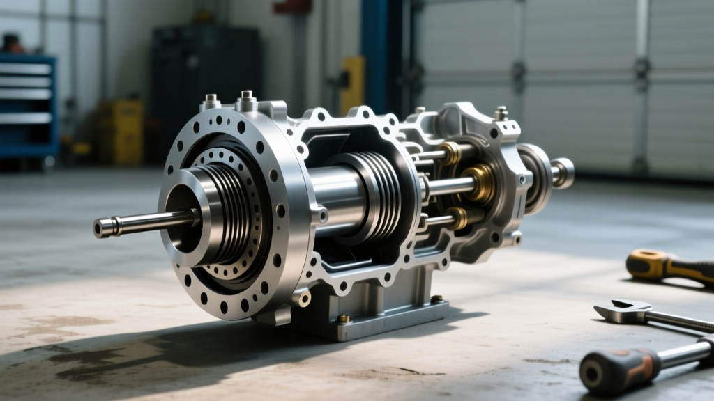
When reviewing a clutch slave cylinder diagram, you will notice two distinct architectural layouts: Concentric Slave Cylinders (CSC) and Remote Push/Pull Cylinders. Choosing the right one depends on your transmission bellhousing and clutch type.
| Feature | Concentric Slave Cylinder (CSC) | Remote Push/Pull Slave Cylinder |
|---|---|---|
| Mounting Location | Inside the bellhousing, wrapping around the transmission input shaft. | Outside the bellhousing, pushing a clutch fork or pull-rod. |
| Typical Applications | Tremec T56 Magnum, Porsche G50, modern GM LS/LT swaps. | Classic Ford Toploader, Muncie M22, aftermarket drag racing setups. |
| Advantages | Perfectly concentric actuation; eliminates clutch fork pivot wear; saves space. | Easy external bleeding; simple to inspect and replace without dropping the transmission. |
| Disadvantages | Requires transmission removal if the seal fails; exposed to extreme clutch dust and heat. | Introduces mechanical pivot points (forks/pins) that can deflect under high clamp loads. |
| Estimated Cost (2026) | $850 - $1,400 (e.g., Tilton 6000 Series) | $350 - $600 (e.g., McLeod Adjustable Hydraulic Bearing) |
For modern performance builds, the CSC is the gold standard. According to Tilton Engineering, their 6000-series CSCs are designed to handle the extreme diaphragm spring pressures of carbon-on-carbon racing clutches, provided the hydraulic ratio is correctly matched.
The Math: Calculating Your Hydraulic Ratio
The most common mistake beginners make when interpreting a clutch slave cylinder diagram is ignoring the hydraulic ratio. The hydraulic ratio dictates your pedal effort and the amount of travel at the throw-out bearing. It is calculated by dividing the area of the slave cylinder piston by the area of the master cylinder piston.
Step-by-Step Calculation
Let us assume you are using a 3/4-inch (0.75") bore master cylinder and a 1.0-inch bore slave cylinder.
- Calculate Master Area: Radius = 0.375". Area = π × (0.375)² = 0.441 square inches.
- Calculate Slave Area: Radius = 0.50". Area = π × (0.50)² = 0.785 square inches.
- Determine Ratio: 0.785 / 0.441 = 1.78:1.
A ratio of 1.78:1 means the force you apply to the pedal is multiplied by 1.78 at the clutch fingers. However, the trade-off is travel: the slave cylinder will only move 56% of the distance the master cylinder pushes. If your pedal ratio is 6:1, your total system ratio becomes roughly 10.6:1. This provides a firm, race-car-like pedal with excellent modulation, ideal for heavy-duty twin-disc clutches from manufacturers like McLeod Racing.
Fluid Selection and Thermal Management
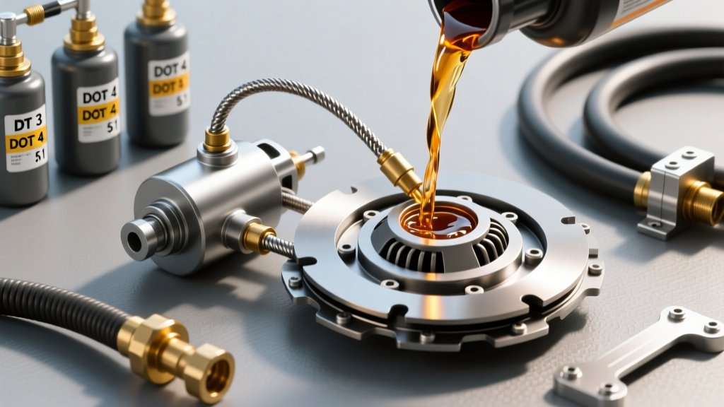
A performance clutch slave cylinder diagram is only as effective as the fluid inside it. Track cars generate immense heat in the bellhousing, which transfers directly into the CSC. Standard DOT 3 fluid will boil under these conditions, causing the pedal to instantly drop to the floor.
For 2026 track builds, high-performance DOT 4 or DOT 5.1 racing fluids are mandatory. Motul RBF 660 is a benchmark choice, offering a dry boiling point of 617°F (325°C). Unlike silicone-based DOT 5 fluids, which compress and feel spongy, glycol-based racing fluids maintain a rigid, incompressible feel even when subjected to the 1,500+ PSI spikes generated during aggressive downshifts.
Pro-Level Bleeding Procedures for Performance Systems
Because performance systems use smaller AN-3 lines and high-pressure seals, traditional 'pump-and-hold' bleeding methods often fail to dislodge micro-bubbles trapped in the slave cylinder's internal crevices. Follow this professional bleeding protocol:
- Use a Power Bleeder: Attach a pressure bleeder (like the Motive Products 0108) to the master cylinder reservoir. Pressurize the system to exactly 15 PSI. Do not exceed 20 PSI, or you risk blowing out the reservoir cap seal.
- Open the Bleeder Screw: Using a 5/16-inch box-end wrench, crack the slave cylinder bleeder screw. Torque spec for re-tightening brass bleeder screws is incredibly low—typically just 4 to 6 ft-lbs. Over-torquing will snap the bleeder nipple off inside the housing.
- Monitor the Flow: Route the waste tube into a clear catch bottle. Watch for a solid, bubble-free stream of amber or purple fluid (depending on your brand).
- Check the Gap: For adjustable hydraulic throw-out bearings, use a feeler gauge to verify the air gap between the bearing face and the pressure plate fingers. Most manufacturers specify a 0.100-inch to 0.150-inch gap to prevent premature clutch wear when the system heats up and the fluid expands.
Summary
Mastering the clutch slave cylinder diagram is the bridge between a frustrating, spongy clutch pedal and a precision-tuned driving experience. By understanding the relationship between bore sizes, selecting the correct CSC or remote setup for your transmission, and utilizing high-temperature racing fluids, you ensure that every ounce of torque from your engine is reliably transferred to the wheels. Whether you are building a weekend track-day terror or a high-horsepower street machine, respect the hydraulics, and the car will reward you with flawless shifts every single time.