Understanding the Output Speed Sensor (OSS) in Modern Drivetrains
The Output Speed Sensor (OSS) is a foundational component of modern transmission management. By monitoring the rotational speed of the transmission's output shaft, the OSS provides the Transmission Control Module (TCM) with real-time data required to calculate gear ratios, determine shift points, and operate the electronic torque converter clutch (TCC). When a driver or technician asks, "where is the transmission sensor located," the answer varies drastically depending on the transmission's architecture and manufacturing era.
Historically, speed sensors were external, variable-reluctance (VR) units that threaded directly into the transmission case. As we navigate the 2026 automotive landscape, however, the industry has largely shifted toward Hall-effect sensors integrated directly into internal mechatronic units or conductor plates. Understanding the exact location, access method, and signal type of your specific OSS is the first step in accurate diagnostics and repair.
Where Is the Transmission Sensor Located? A Model-by-Model Breakdown
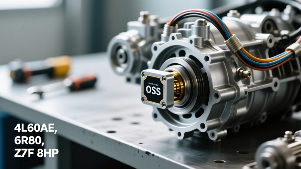
Because transmission architectures differ between manufacturers, the physical location of the OSS ranges from a simple external tail-housing plug to an internal, non-serviceable component soldered to a valve body. Below is a technical breakdown of the three most common platforms encountered in repair bays today.
GM 4L60E and 4L80E Series
For the ubiquitous GM 4L60E and 4L80E transmissions, the OSS is an externally mounted, two-wire Variable Reluctance (VR) sensor (on older models) or a three-wire Hall-effect sensor (on later iterations). It is located on the rear extension housing (tail housing), typically on the passenger side, just above the output shaft yoke. The sensor reads the teeth of a reluctor ring pressed onto the output shaft. Access is straightforward: the vehicle is raised, the driveshaft is marked and removed, and the sensor is extracted using a single 10mm hex bolt.
Ford 6R80 and 10R80
On Ford's 6R80 and the widely adopted 10R80 10-speed automatics, the OSS is also located on the rear case extension housing. However, unlike the GM units, the Ford OSS reads a specialized stamped-steel reluctor ring integrated into the parking pawl gear assembly. The sensor is secured by an M6 bolt. Because these sensors operate in high-vibration environments, Ford utilizes a specialized O-ring seal and a precise air-gap specification to prevent signal dropout at high highway speeds.
ZF 8HP (Chrysler, BMW, Audi, Jaguar)
The ZF 8HP 8-speed automatic represents a massive shift in sensor packaging. If you are searching for the OSS on a ZF 8HP, you will not find it on the exterior case. Instead, the input and output RPM sensors are permanently soldered onto the internal conductor plate, which is part of the Mechatronic valve body assembly. To access it, the transmission pan must be dropped, the fluid filtered, and the entire Mechatronic unit unbolted from the transmission case. You cannot replace just the sensor; the entire conductor plate or Mechatronic assembly must be replaced.
Location and Specification Reference Chart
| Transmission Model | OSS Location | Access Method | OEM Part Number Example | Approx. Part Cost |
|---|---|---|---|---|
| GM 4L60E (Late) | Rear Extension Housing | External (Under vehicle) | ACDelco 213-1722 | $25 - $45 |
| Ford 6R80 | Rear Case / Extension | External (Under vehicle) | Motorcraft SW-6846 | $35 - $60 |
| GM 6L80 / 6L90 | Internal Case / TEHCM | Pan removal, Valve Body drop | Integrated into TEHCM | $800+ (TEHCM Assy) |
| ZF 8HP45 / 8HP70 | Mechatronic Conductor Plate | Pan removal, Mechatronic drop | ZF 1068.298.035 | $450 - $750 |
Diagnostic Trouble Codes (DTCs) and TCM Logic
When the TCM detects an anomaly with the OSS, it will illuminate the malfunction indicator lamp (MIL) and store specific OBD-II codes. The most common codes include:
- P0720: Output Speed Sensor Circuit Malfunction (General electrical fault, open/short).
- P0721: Output Speed Sensor Circuit Range/Performance (Rationality fault).
- P0722: Output Speed Sensor Circuit No Signal.
- P0723: Output Speed Sensor Circuit Intermittent.
The TCM relies on a continuous rationality test. It compares the Input Speed Sensor (ISS) data against the OSS data to calculate the actual gear ratio. For example, if the TCM commands 4th gear (which has a known mathematical ratio of 1.15:1), but the ISS and OSS data indicate a ratio of 1.4:1, the TCM recognizes a discrepancy. While this can indicate mechanical slipping, a failing OSS will cause erratic ratio calculations, often triggering both a P0721 code and secondary gear-ratio codes (e.g., P0734 for 4th gear incorrect ratio).
Step-by-Step Replacement and Torque Specifications
For externally mounted sensors (like the 4L60E or 6R80), replacement requires strict adherence to torque and sealing protocols to prevent fluid leaks and sensor damage.
- Preparation: Disconnect the negative battery terminal to prevent TCM voltage spikes. Clean the area around the sensor bore with brake cleaner to prevent debris from entering the transmission case.
- Removal: Unclip the electrical connector. Remove the retaining bolt (usually 10mm or M6). Gently twist and pull the sensor from the bore. Never pry the sensor with a screwdriver, as the plastic housing will snap and leave fragments inside the case.
- Inspection: Inspect the sensor tip for metallic fuzz. A light coating of fine metallic dust is normal due to the magnetic pickup, but large chunks of debris indicate internal mechanical failure.
- Installation: Lubricate the new sensor's O-ring with the manufacturer-specified ATF (e.g., Dexron VI or Mercon LV). Do not use petroleum jelly or silicone grease, as these will swell and destroy the EPDM rubber O-ring.
- Torque: Reinstall the retaining bolt and torque to 8 to 10 Nm (71 to 89 lb-in)
Expert Air-Gap Warning: Hall-effect and VR sensors rely on a precise air gap between the sensor tip and the reluctor ring, typically between 0.5mm and 1.2mm. If the O-ring is pinched during installation, the sensor will sit too far back, resulting in a weak signal that drops out at high RPMs, mimicking a mechanical slip condition.
Advanced Testing: Oscilloscope and Multimeter Procedures
Before replacing an OSS, professional technicians verify the signal integrity. Because modern OSS units are predominantly Hall-effect sensors, a simple ohmmeter resistance test is insufficient and can damage the internal microchips.
Pinout Verification: A standard 3-wire Hall-effect OSS will have a 5-Volt Reference (from the TCM), a Low-Reference Ground, and a Signal Return wire. Using a digital multimeter, back-probe the connector with the key on, engine off. You should read exactly 5.0V on the reference wire and less than 0.05V of voltage drop on the ground wire.
Oscilloscope Testing: Connect an oscilloscope to the signal wire. Slowly rotate the drive wheels (with the vehicle safely lifted and in neutral). A healthy Hall-effect sensor will produce a crisp, digital square wave toggling between 0V and 5V. A failing sensor will show rounded edges, voltage dropouts, or an amplitude that fails to reach the full 5V threshold. If the square wave is distorted but the wiring tests good, the sensor or the internal reluctor ring is at fault.
Authoritative Sources and Further Reading
For advanced diagnostics and OEM engineering specifications, technicians should consult primary manufacturer documentation and engineering papers: