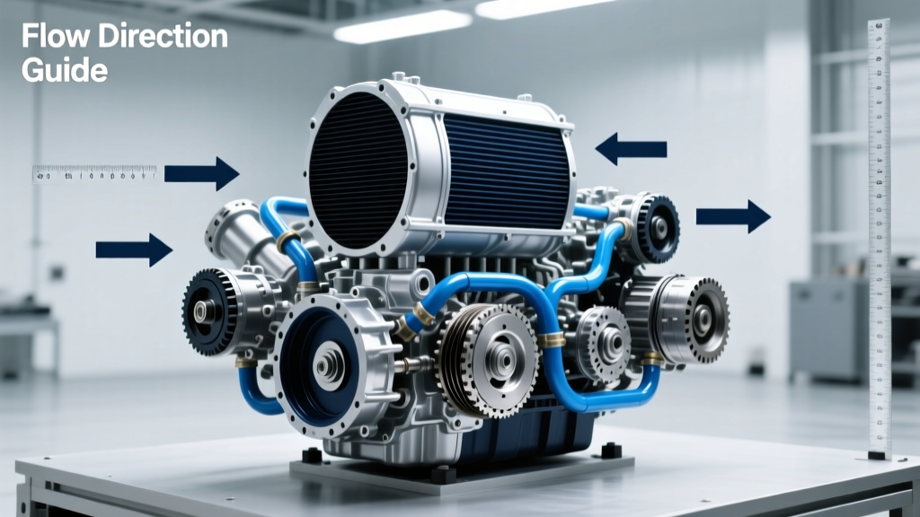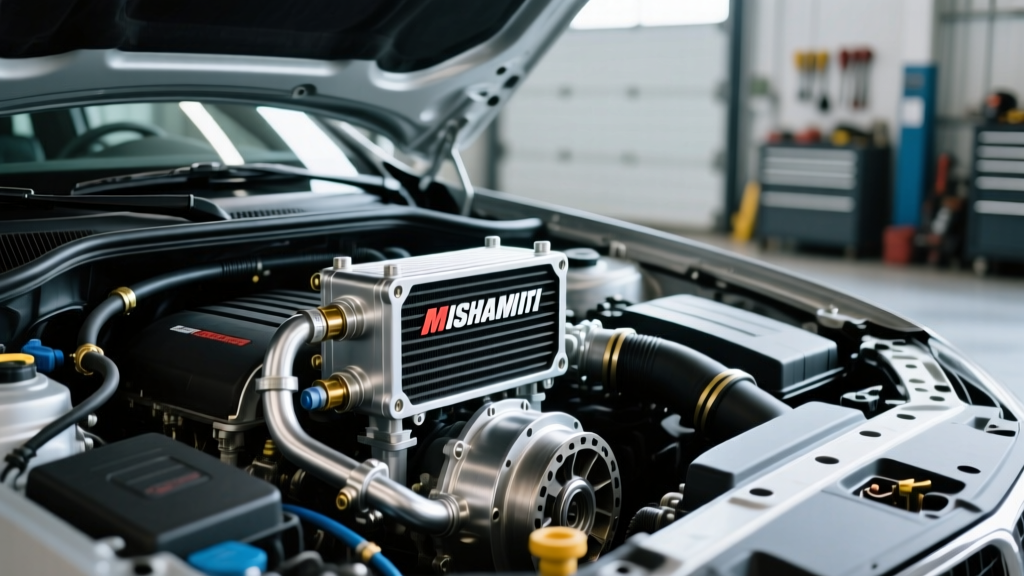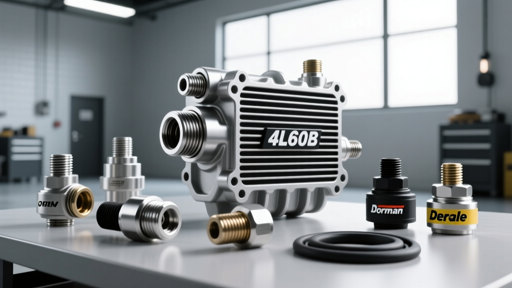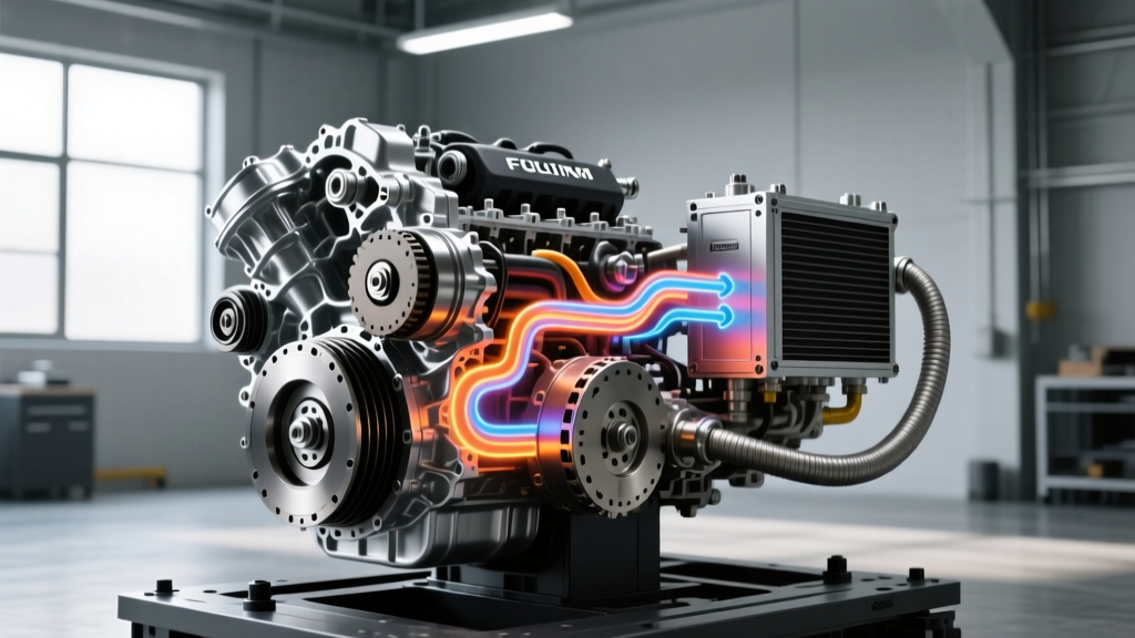
In the modern automotive landscape of 2026, transmissions are engineered to handle immense torque loads, but this increased performance comes with a severe thermal penalty. Whether you are towing a 10,000-pound trailer with a GM 6L80-equipped Silverado or navigating stop-and-go traffic in a ZF 8HP-powered European SUV, thermal management is the single most critical factor in drivetrain longevity. When fluid temperatures exceed 220°F (104°C), the fluid begins to oxidize, varnish forms on valve bodies, and clutch packs glaze and slip. The most effective way to diagnose, prevent, and resolve these thermal failures is by utilizing a transmission cooler lines diagram to verify proper hydraulic routing and auxiliary cooler integration.
This step-by-step guide will walk you through interpreting OEM flow schematics, diagnosing hidden overheating causes, and correctly installing an auxiliary stacked-plate cooler to safeguard your transmission.
The Thermodynamics of Transmission Overheating
Before turning a wrench, it is vital to understand why specific transmission models are prone to overheating. The GM 6L80 and 6L90, for instance, are notorious for 3-5-R clutch pack failure when lube flow is restricted or misrouted. The torque converter generates the bulk of the heat during slip phases (e.g., heavy acceleration or towing). This superheated fluid must exit the transmission case, pass through the radiator’s internal heat exchanger, and then flow through an external cooler before returning to the transmission lube circuit.
If the fluid routing is compromised, or if an auxiliary cooler is installed backward, the transmission control module (TCM) will register rising temperatures, eventually triggering limp mode to prevent catastrophic mechanical failure. According to Sonnax Technical Resources, improper lube flow and cooler circuit restrictions are leading contributors to premature clutch wear in modern 6-speed and 8-speed automatics.
Step 1: Sourcing and Reading Your Transmission Cooler Lines Diagram
Guessing which line is the pressure-out (to cooler) and which is the return (from cooler) is a rookie mistake that leads to reversed flow through auxiliary coolers and OEM thermal bypass valves. To prevent this, you must obtain the exact factory schematic for your specific year, make, and model.
- Access OEM Data: Subscribe to a service like AlldataDIY, Mitchell1, or GM TechConnect. Navigate to the ‘Transmission Cooling’ or ‘Hydraulic Schematics’ section.
- Identify the ‘To Cooler’ Line: On the diagram, trace the line exiting the transmission case. On the GM 6L80 (RWD applications), this is typically the rear-most fitting on the passenger side of the case. This line carries the hottest fluid directly from the torque converter and lube circuit.
- Identify the Thermal Management Module (TMM): Many ZF 8HP and Ford 10R80 transmissions utilize a wax-thermostat bypass valve in the cooler lines. The diagram will show exactly which direction the fluid must flow to open the thermostat correctly. Routing fluid backward through a ZF 8HP TMM will cause the valve to remain closed, sending fluid back to the transmission uncooled.
- Locate the ‘From Cooler’ Return Line: This line returns cooled fluid to the transmission’s lube regulator valve, ensuring the planetary gearsets and clutch packs receive adequately cooled lubrication.
Step 2: Diagnosing Overheating Causes via Flow Routing
Once you have your transmission cooler lines diagram, you can systematically diagnose why your unit is running hot. Connect an inline infrared thermometer or a digital thermocouple to the metal sections of the cooler lines to isolate the restriction.
Cause 1: Internal Radiator Tank Restrictions
The OEM transmission cooler located inside the engine’s radiator is the first point of cooling. If the fluid entering the radiator is 230°F, but the fluid exiting the radiator into the external lines is still 225°F, the internal radiator cooler is clogged with debris or degraded clutch material. Solution: Replace the radiator or bypass the OEM internal cooler entirely in favor of a massive front-mount stacked-plate unit.
Cause 2: Stuck Thermal Bypass Valves
Many modern vehicles feature a thermal bypass valve that prevents fluid from going to the cooler when the engine is cold, allowing the transmission to reach operating temperature quickly. If this valve sticks in the ‘bypass’ position due to sludge or a failed wax element, the fluid never reaches the cooler. Using your diagram, locate the bypass valve and test it with a heat gun and thermometer. If it fails to open at 180°F (82°C), replace the valve assembly.
Cause 3: Collapsed Rubber Hoses
OEM rubber cooler hoses degrade over time. The internal lining can separate and collapse under the suction of the return line, acting as a tourniquet on the hydraulic system. Inspect all flexible hose segments indicated on your diagram and replace them with high-temp synthetic rubber or braided stainless steel lines.
Step 3: Installing an Auxiliary Stacked-Plate Cooler
If you tow frequently or live in a high-ambient-temperature climate, adding an auxiliary stacked-plate cooler (such as the Hayden 678 Rapid-Cool or Derale 13504 T-Cool) is mandatory. Stacked-plate designs offer 30% more surface area and lower pressure drops compared to traditional tube-and-fin designs. As noted in Hayden Automotive Tech Tips, mounting the cooler in front of the A/C condenser and radiator is crucial for maximum airflow.
- Disconnect the Battery: Prevent any electrical shorts or accidental TCM resets.
- Relieve Line Pressure: Place a drain pan beneath the transmission. Use a specialized quick-disconnect tool (e.g., Lisle 39960 set) to release the OEM 5/8-inch or 3/4-inch quick-connect fittings at the radiator.
- Install Adapter Fittings: For GM 6L80 applications, the transmission case uses M12x1.5 O-ring boss fittings. If adapting to AN-lines or hose barbs, torque the aluminum adapter fittings to exactly 18 lb-ft (25 Nm). Overtightening will crack the transmission case.
- Route the Lines per the Diagram: Cut the OEM ‘To Cooler’ line (or use the quick-disconnect adapter) and route it to the INLET of the auxiliary stacked-plate cooler. Route the OUTLET of the auxiliary cooler to the OEM radiator inlet (for a series setup) or directly back to the transmission ‘From Cooler’ return line (for a standalone setup).
- Secure and Zip-Tie: Use rubber-cushioned Adel clamps to secure the new lines to the frame rail, maintaining at least 2 inches of clearance from the exhaust system.
Thermal Testing and Flow Verification
After installation, you must verify the flow rate and thermal drop. Start the engine, let it reach normal operating temperature, and measure the temperature differential across the new cooler. Use the table below as a benchmark for your specific transmission model.
| Transmission Model | Normal Op. Temp | Danger Zone | Target Flow Rate | Cooler Line Fitting Spec |
|---|---|---|---|---|
| GM 6L80 / 6L90 | 180°F - 200°F | 220°F+ | 1.5 - 2.0 GPM | M12x1.5 O-Ring Boss |
| ZF 8HP45 / 8HP70 | 170°F - 195°F | 215°F+ | 1.2 - 1.8 GPM | Quick-Disconnect / Banjo |
| Ford 10R80 | 185°F - 205°F | 225°F+ | 2.0 - 2.5 GPM | 5/8" Quick-Disconnect |
| Aisin 09D / 09G | 175°F - 190°F | 210°F+ | 1.0 - 1.5 GPM | M10x1.0 Banjo Bolt |
To test flow rate safely, disconnect the return line at the transmission, route it into a calibrated 1-gallon jug, and run the engine for exactly 30 seconds at idle. Multiply the volume collected by 2 to get Gallons Per Minute (GPM). If your flow rate is below the target specs in the table, you have a restriction in the torque converter, a failing lube regulator valve, or a kinked line.
Preventative Maintenance and Fluid Economics
A properly routed cooling system is only half the battle; the chemical stability of the fluid is the other. In 2026, synthetic fluid technology has advanced, but using the incorrect fluid will still lead to rapid thermal breakdown.
- GM Applications: Require Dexron VI or the newer Dexron ULV (Ultra Low Viscosity) for 10-speed units. A full flush and fill costs between $250 and $350 at a specialist shop, or roughly $90 in DIY materials (approx. 12 quarts).
- ZF Applications: Strictly require ZF LifeguardFluid 8. Using generic ATF will cause the mechatronic sleeve seals to swell and fail under high heat. OEM ZF fluid costs approximately $25-$35 per liter.
- Filter Maintenance: The 6L80 features a shallow pan filter that should be dropped and replaced every 60,000 miles. The ZF 8HP features a molded plastic pan with an integrated filter; the entire pan assembly (approx. $180-$250) must be replaced during a fluid service.
For deeper insights into fluid degradation and hydraulic valve body wear, industry publications like Transmission Digest regularly publish teardown analyses showing the direct correlation between cooler line restrictions and solenoid failure.
Conclusion
Transmission overheating is rarely a sudden, unexplainable failure; it is almost always the result of compromised fluid routing, neglected thermal bypass valves, or inadequate cooling capacity. By obtaining the correct transmission cooler lines diagram, you eliminate the guesswork from diagnostics and aftermarket cooler installations. Whether you are verifying the M12x1.5 torque specs on a 6L80 or ensuring the wax thermostat on a ZF 8HP is flowing in the correct direction, precision and adherence to OEM schematics will keep your drivetrain temperatures in check and your vehicle out of limp mode.