Why Transmission Cooler Size Selection Dictates Drivetrain Survival
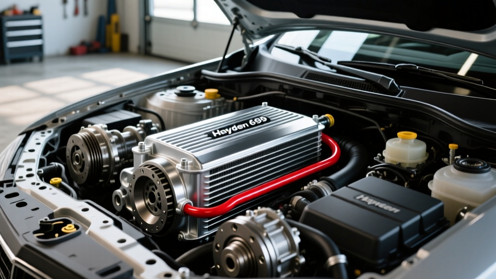
Automatic transmission fluid (ATF) serves as both a hydraulic medium and a critical coolant. When ATF temperatures exceed 220°F (104°C), the fluid begins to oxidize, varnish forms on valve body spools, and clutch pack friction materials rapidly degrade. For heavy-duty towing, off-road crawling, or track use, the factory radiator-integrated cooler is rarely sufficient. Proper transmission cooler size selection is not a guessing game; it requires calculating your Gross Vehicle Weight (GVW), understanding core architecture, and correctly mapping your plumbing. In this step-by-step guide, we will walk through sizing a cooler for popular transmissions like the GM 6L80, the classic 4L60E, and the ZF 8HP, while ensuring your transmission cooler flow direction is optimized for maximum thermal transfer.
Step 1: Calculate Your True Gross Vehicle Weight (GVW)
Cooler manufacturers rate their products based on GVW, which is the combined weight of the vehicle, passengers, cargo, and the trailer being towed. Selecting a cooler rated below your actual GVW will result in inadequate heat dissipation, while drastically oversizing can lead to ATF overcooling in cold climates, preventing the transmission from reaching optimal operating temperature (typically 175°F to 195°F).
| GVW Class | Total Weight Range | Recommended Cooler Dimensions | Example Part Numbers | Est. Cost (2026) |
|---|---|---|---|---|
| Light Duty | Up to 10,000 lbs | 7.5" x 12.5" x 0.75" | Hayden 676 (Rapid-Cool) | $55 - $75 |
| Medium Towing | 10,001 - 16,000 lbs | 9.5" x 13" x 0.75" | Hayden 678 / Derale 13503 | $75 - $110 |
| Heavy Towing | 16,001 - 24,000 lbs | 11" x 15.5" x 1.0" | Derale 13316 (Hyper-Cool) | $140 - $180 |
| Severe Duty | 24,000+ lbs | Dual 11" x 15.5" or Fan-Driven | Mishimoto MMTC-F2D w/ Fan | $280 - $350 |
Pro Tip: If your vehicle is a 3/4-ton truck (e.g., Silverado 2500HD) weighing 7,500 lbs and you frequently tow an 8,500 lb trailer, your GVW is 16,000 lbs. You must step up to the Heavy Towing class to account for stop-and-go traffic and steep grades.
Step 2: Select the Optimal Core Architecture
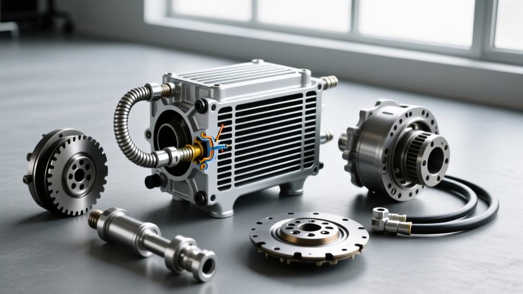
Size is only one variable; the internal design of the cooler dictates how efficiently it sheds heat. According to Derale Performance, there are three primary architectures:
- Tube-and-Fin: The oldest and least efficient design. Best for light-duty passenger cars where budget is the primary concern.
- Plate-and-Fin: Features internal turbulators that agitate the ATF, increasing surface area contact. Excellent for medium towing and daily drivers.
- Stacked-Plate: The gold standard for heavy towing and motorsport. Plates are stacked and brazed together, offering the highest surface-area-to-volume ratio and superior structural integrity against vibration and debris impact.
Step 3: Map the Transmission Cooler Flow Direction
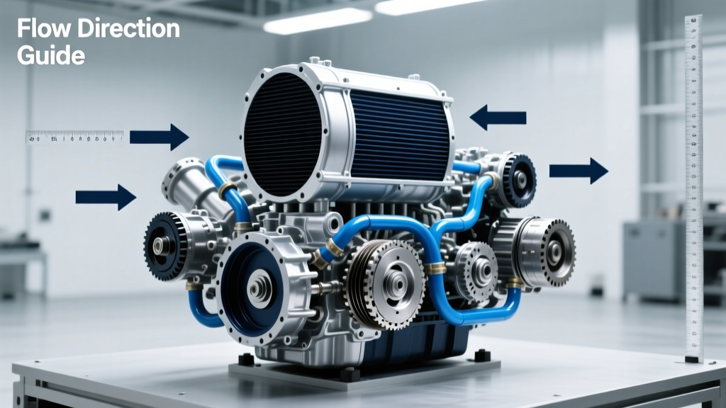
One of the most critical—and frequently botched—steps in the installation process is verifying the transmission cooler flow direction. While many basic tube-and-fin coolers are bidirectional, modern stacked-plate coolers and units with integrated thermal bypass valves often have strict inlet and outlet requirements. Reversing the flow can cause the internal thermostat to remain closed, completely bypassing the cooler core and sending hot fluid directly back to the transmission.
The Bucket Test for GM 4L60E and 6L80 Applications
On GM applications like the 4L60E and the 6L80, the factory routing typically sends fluid from the transmission to the radiator, and then out to an auxiliary cooler. However, identifying the exact 'pressure out' and 'return in' lines at the transmission pan is vital.
- Locate the two metal transmission cooler lines at the rear of the transmission case.
- Disconnect both lines at the transmission fittings and place the ends into two separate, clearly marked buckets.
- Have an assistant start the engine and let it idle for exactly 3 to 5 seconds. Do not rev the engine.
- Shut off the engine. The bucket with the significant volume of ATF is your 'Pressure Out' (to the cooler). The bucket with little to no fluid is your 'Return In' (from the cooler).
- Measure the fluid pumped to ensure you top off the transmission pan accurately before final assembly.
ZF 8HP Thermal Management Module (TMM) Considerations
The ZF 8HP transmission (found in Ram 1500s, BMWs, and Jaguars) utilizes a complex Thermal Management Module. As noted by Sonnax, the ZF 8HP's thermal bypass valve is notorious for sticking, causing premature overheating. When installing an auxiliary cooler on a ZF 8HP, you must tap into the lines after the TMM but before the fluid returns to the pan. Mapping the transmission cooler flow direction here requires an infrared thermometer: run the vehicle until the TMM opens (usually around 180°F), and trace the lines to find the hottest hose. That is your feed line to the auxiliary cooler.
Step 4: Line Sizing, Fittings, and Bypass Valves
Restricting flow is just as dangerous as overheating. A cooler that is too small in physical volume or paired with undersized lines will cause a pressure drop, starving the transmission lube circuit.
- 3/8" Lines: Standard for most 4L60E, 6L80, and light-duty ZF 8HP applications. Ensure your chosen cooler features 3/8" barb or -6 AN fittings.
- 1/2" Lines: Required for heavy-duty applications like the GM 10L90 or Ford 10R80 when towing max capacity. Using a 3/8" cooler on a 1/2" system creates a bottleneck.
If you live in a climate where winter temperatures drop below freezing, install a thermostatic bypass valve (e.g., Derale 13011). This valve routes fluid away from the cooler until the ATF reaches 180°F, preventing the fluid from becoming too viscous and causing cavitation in the transmission pump.
Step 5: Mounting, Plumbing, and Torque Specifications
Proper mounting ensures structural longevity and optimal airflow. The cooler must be mounted in front of the A/C condenser and radiator. If space is limited, a puller-style electric fan (like the Hayden 3647) mounted directly to the cooler is mandatory.
CRITICAL TORQUE SPECS: Over-tightening cooler line fittings is the leading cause of cracked aluminum headers and stripped radiator threads. Always use a calibrated torque wrench.
- OEM 3/8" Inverted Flare Tube Nuts (Steel to Aluminum Radiator): 15 - 18 lb-ft. Use a crowfoot wrench to avoid rounding the soft brass or aluminum fittings.
- -6 AN Hose Ends to Stacked-Plate Cooler: 10 - 12 lb-ft. Use two wrenches (one to hold the cooler header boss, one to turn the nut) to prevent twisting the brazed plates.
- Cooler Mounting Brackets to Core Support: 8 - 10 lb-ft. Use rubber isolator pads between the cooler bracket and the chassis to prevent high-frequency vibration from fracturing the aluminum inlet tubes.
Final System Verification
After plumbing the system and verifying the transmission cooler flow direction, fill the transmission with the correct OEM-specified fluid (e.g., Dexron ULV for GM 10-speeds, ZF Lifeguard 8 for the 8HP). Start the engine, cycle through all gears while holding the brake pedal to fill the torque converter, and check for leaks. Use an OBD2 scanner to monitor the Transmission Fluid Temperature (TFT) PID. Under a heavy load or simulated towing condition, a properly sized and plumbed auxiliary cooler should maintain TFT between 185°F and 205°F, ensuring your drivetrain survives the harshest 2026 towing demands.
For further reading on thermal dynamics and cooler sizing charts, consult the engineering resources available at Hayden Automotive.