The Hidden Geometry of Drivetrain Mating
When diagnosing automatic transmission failures, technicians often overlook the physical interface between the engine and the transmission. However, torque converter bolt pattern and fitment are foundational to optimal torque converter function. If the flexplate-to-converter mating surface, bolt circle diameter (BCD), or pilot hub clearance deviates from factory specifications by mere thousandths of an inch, the resulting mechanical bind will manifest as severe drivability symptoms, catastrophic pump failure, or torque converter clutch (TCC) shudder.
As of 2026, with the proliferation of high-torque forced-induction platforms and complex 8-to-10-speed automatics like the ZF 8HP and Ford 10R80, precision in drivetrain mating is less forgiving than ever. The hydrodynamic coupling relies on perfect concentricity. When bolt pattern fitment is compromised, the torque converter operates under a state of continuous mechanical stress, leading to a cascade of internal failures that mimic internal hydraulic or electrical faults.
The Anatomy of Flexplate and Converter Mating
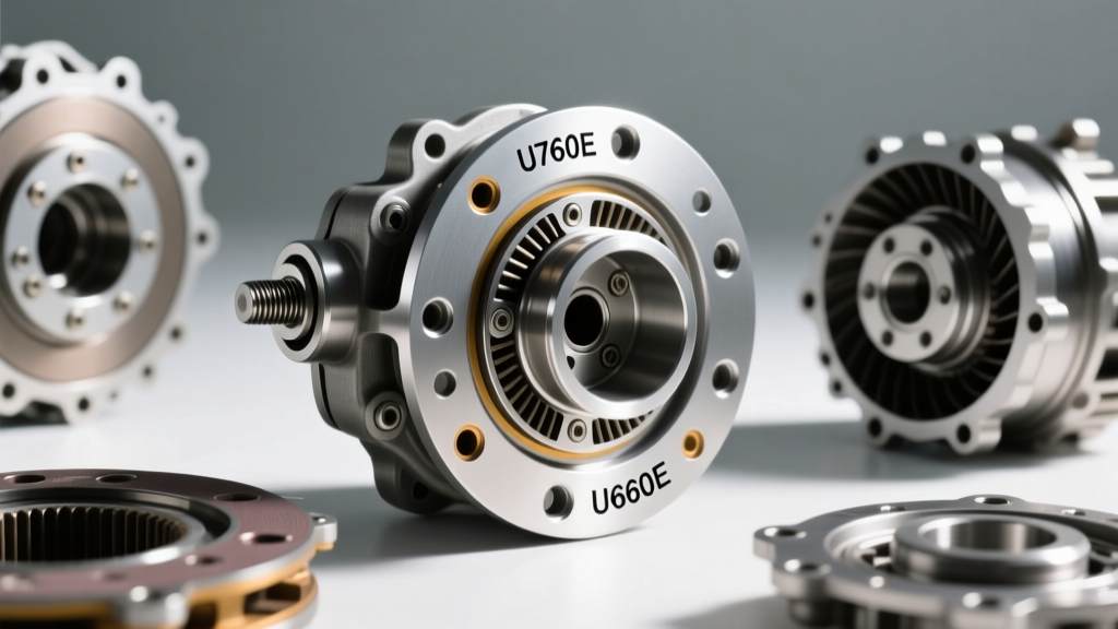
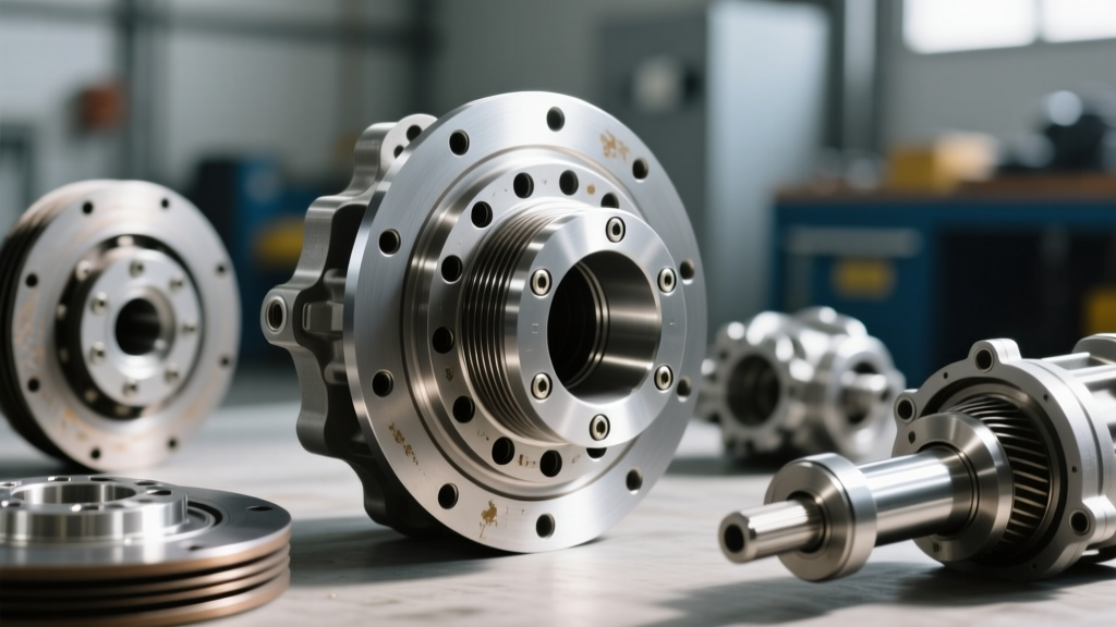
The connection between the engine's crankshaft and the transmission's input shaft is mediated by two critical components: the flexplate (or flywheel) and the torque converter's front cover. Understanding the geometry of this connection is vital for preserving torque converter function.
Bolt Circle Diameter (BCD) and Pad Alignment
The Bolt Circle Diameter (BCD) dictates the exact circumference on which the flexplate mounting bolts pass through the converter's front cover. General Motors, Ford, and Chrysler utilize varying BCDs, and even within a single manufacturer, patterns differ based on torque capacity. For example, the GM 4L60E family traditionally uses a 10.75-inch 3-bolt pattern (often with dual-drilled pads for 11.5-inch applications), while the heavier-duty 6L80 and 6L90 utilize a robust 11.5-inch 6-bolt pattern. If an aftermarket flexplate with the incorrect BCD or improperly stamped mounting pads is used, the converter is forced into an off-center orbit as the bolts are torqued down, instantly inducing runout.
Pilot Hub and Crankshaft Bore Dynamics
The pilot hub is the machined snout on the front of the torque converter that centers the assembly inside the crankshaft bore. This hub must also support the transmission's front pump bushing. Proper torque converter function requires the pilot hub to slide into the crank bore with a specific clearance—typically between 0.005" and 0.015". If the clearance is too tight (pilot bind), the converter cannot expand outward under centrifugal force and hydraulic pressure, pushing forward against the crankshaft thrust bearing. If the clearance is too loose, the converter orbits, destroying the front pump bushing and stator support tube.
Critical Measurements and Torque Specifications
Reference the following data table to ensure precise fitment during transmission installation or engine swaps. Deviating from these specifications will immediately degrade torque converter function.
| Transmission Model | Bolt Circle / Pattern | Pilot Hub Diameter | Flexplate Bolt Torque |
|---|---|---|---|
| GM 4L60E / 4L65E | 10.75" (3-bolt) / 11.5" | 1.703" (43.25mm) | 33 lb-ft (45 Nm) |
| GM 6L80 / 6L90 | 11.5" (6-bolt) | 2.125" (53.97mm) | 45 lb-ft (61 Nm) |
| ZF 8HP70 / 8HP90 | 10.5" / 11.8" (OEM Dep.) | 1.968" (50.00mm) | 37 lb-ft (50 Nm) |
| Ford 6R80 / 10R80 | 11.43" (6-bolt) | 2.000" (50.80mm) | 40 lb-ft (54 Nm) |
Severe Symptoms of Improper Fitment
Because the torque converter acts as both a fluid coupling and a mechanical lockup device, physical misalignment caused by poor bolt pattern fitment triggers highly specific, often misdiagnosed symptoms.
Symptom 1: Front Pump Bushing and Stator Destruction
When the BCD is mismatched or the flexplate is warped, the torque converter is pulled off-center. According to Sonnax Technical Resources, this off-center rotation forces the converter's pilot hub to act like a cam against the front pump bushing. The immediate symptom is a high-pitched whine from the bellhousing that changes with engine RPM, followed by a sudden loss of line pressure. Internally, the stator support tube becomes galled, and the pump halves score, requiring a complete transmission teardown.
Symptom 2: TCC Shudder and Lockup Failure
The Torque Converter Clutch (TCC) relies on a perfectly flat, concentric friction surface to apply smoothly. If the converter is bolted to a flexplate with incorrect mounting pad heights (a common issue in cheap aftermarket replacement flexplates), the front cover distorts. This distortion transfers to the internal TCC piston. When the transmission commands lockup, the clutch material engages at an angle, resulting in violent TCC shudder between 35-50 mph. Technicians often misdiagnose this as a bad solenoid or degraded fluid, when in reality, the mechanical runout has destroyed the friction lining.
Symptom 3: Crankshaft Thrust Bearing Catastrophe
If the torque converter pilot bottoms out in the crankshaft bore because the technician failed to leave the required 1/8" to 3/16" gap between the flexplate and the converter pads, a phenomenon known as "pilot bind" occurs. As the engine's crankshaft expands forward under thermal load and combustion forces, it has no thrust clearance. The result is the rapid destruction of the engine's crankshaft thrust bearing, leading to catastrophic engine failure. This symptom often presents as a deep, rhythmic knocking under load that disappears when the transmission is placed in neutral (relieving the forward pressure on the converter).
Aftermarket Swaps and Spacer Protocols
Engine swaps, particularly the ubiquitous GM LS/V8 conversions into older chassis, are notorious for fitment errors that ruin torque converter function. When mating a 4L80E transmission to an early LS block, the crankshaft bore depth and the converter pilot length must be verified. Many LS engines utilize a stepped crank bore designed for the 2.125" pilot of the 4L60E/6L80, while the 4L80E uses a 1.703" pilot.
Pro-Tip for Fabricators: Never rely solely on the transmission bellhousing sitting flush against the engine block to verify fitment. Always measure the distance from the engine block mating surface to the flexplate pad, and compare it to the distance from the transmission bellhousing face to the converter mounting pad. Use precision-machined steel spacer rings if the gap exceeds 1/4", and never use flat washers to bridge a gap, as they will deform under 45 lb-ft of torque and induce severe runout.
For detailed swap geometry, fabricators frequently consult TCI Automotive's fitment guides, which emphasize that using a converter with a shortened hub to compensate for block depth will result in the converter pulling out of the transmission pump, stripping the pump gears upon first startup.
Step-by-Step Fitment Verification Protocol
To guarantee optimal torque converter function and prevent comeback jobs, follow this strict verification protocol before bolting the transmission to the engine block:
- Step 1: Verify Pump Engagement. Slide the torque converter into the transmission. You must feel three distinct "clunks" as the hub passes through the front pump, the stator clutch, and the turbine splines. Measure the distance from the bellhousing face to the converter pad; it must be at least 1/8" recessed.
- Step 2: Check Pilot Clearance. Insert the converter pilot into the crankshaft bore by hand. It should slide in smoothly with slight drag. If it requires a mallet, the pilot is oversized or the crank bore is burred. Use emery cloth to hone the bore if necessary.
- Step 3: Inspect Flexplate Runout. Mount a dial indicator to the engine block and measure the flexplate pad runout while rotating the crankshaft. Maximum allowable runout for proper TCC function is typically 0.015". If it exceeds this, replace the flexplate.
- Step 4: Measure Pad Gap. Bring the transmission flush to the engine block (using alignment dowels). Measure the gap between the flexplate pads and the converter pads. The ideal gap is 1/8" to 3/16". If the converter is pulled forward more than 1/4" to meet the flexplate, the pilot is binding in the crank.
- Step 5: Torque Sequence. Apply a medium-strength threadlocker (e.g., Loctite 243) to the flexplate bolts. Torque them in a star pattern to the manufacturer's exact specification (refer to the table above) to ensure even clamping force across the converter cover.
Conclusion
Torque converter bolt pattern and fitment are not mere assembly details; they are the physical foundation of hydraulic stability and mechanical longevity. Whether you are rebuilding a classic 4L60E or installing a modern ZF 8HP, respecting the precise geometry of the BCD, pilot hub, and mounting pad gap is non-negotiable. By understanding how physical misalignment directly corrupts torque converter function, technicians can eliminate mysterious TCC shudders, prevent front pump devastation, and ensure the drivetrain operates exactly as engineered.
For further reading on transmission assembly tolerances and hydraulic diagnostics, the Transmission Digest archives remain an invaluable resource for professional rebuilders and diagnostic technicians.