What is a Transmission Range Sensor on Ford Vehicles?
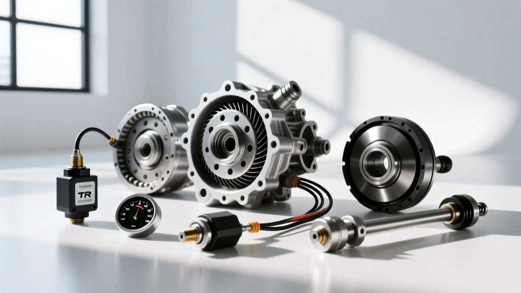
When diagnosing shifting anomalies or starting issues in modern Blue Oval trucks and cars, understanding the transmission range sensor Ford technicians rely on is critical. Often referred to as the PRNDL switch, neutral safety switch, or gear position sensor, the Transmission Range Sensor (TRS) is the vital bridge between your physical gear shifter and the vehicle's Powertrain Control Module (PCM). In popular Ford transmissions like the rear-wheel-drive 6R80 (found in 2011-2017 F-150s) and the front-wheel-drive 6F35 (found in the Escape and Fusion), the TRS tells the PCM exactly what gear the driver has selected.
This sensor does far more than just illuminate the 'R' or 'D' on your dashboard. It dictates whether the starter relay will engage (allowing the engine to crank only in Park or Neutral), controls the reverse backup lights, and provides the baseline data the Transmission Control Module (TCM) uses to calculate line pressure and shift schedules. If the PCM receives conflicting data—for example, if the shifter is in Drive but the TRS reports Neutral—the transmission will default to a failsafe 'limp mode,' locking you in a single gear to protect the internal clutches from catastrophic damage.
Common Symptoms and OBD2 Diagnostic Codes
Before grabbing a digital multimeter (DMM), it is essential to verify that your symptoms align with a TRS failure. Because the sensor is exposed to road debris, moisture, and extreme thermal cycles under the vehicle, internal corrosion and micro-fractures in the resistor ladder are common failure points.
- No-Crank / No-Start Condition: The PCM does not see a 'Park' or 'Neutral' signal, preventing the starter relay from grounding.
- Erratic Shifting or Limp Mode: The transmission defaults to 3rd or 5th gear, and the wrench icon may illuminate on the dash.
- Reverse Lights Malfunction: Backup lights remain on constantly or fail to illuminate when reversing.
- Diagnostic Trouble Codes (DTCs): You will typically see OBD2 P0705 (Transmission Range Sensor Circuit Malfunction), P0706 (Range/Performance), P0707 (Low Input), or P0708 (High Input) when scanning the vehicle.
Tools Required for the Job
Testing a transmission range sensor requires precision. Avoid piercing wire insulation with sharp probes, as this invites moisture ingress and future corrosion. Instead, gather the following tools:
- Digital Multimeter (DMM): Must be capable of reading DC Voltage (V) and Resistance/Continuity (Ohms).
- T-Pin Back-Probes: For safely testing the connector while it is mated to the sensor.
- Basic Socket Set: Including a 10mm socket and an 8mm socket for Ford TRS mounting bolts.
- Wiring Diagram / Pinout Chart: Essential for identifying the 5V reference, ground, and signal return circuits.
- TRS Alignment Tool: Ford special tool 307-585 (or an equivalent aftermarket alignment pin) if removal and replacement are required.
Step-by-Step Transmission Range Sensor Ford Testing Procedure
For this guide, we will focus on the widely used external side-mounted TRS found on the Ford 6R80 transmission. Always prioritize safety by chocking the wheels and engaging the parking brake before crawling underneath the vehicle.
Step 1: Visual and Wiring Inspection
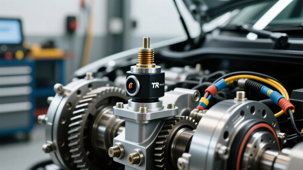
Locate the TRS on the driver's side of the transmission case, directly where the shift linkage cable attaches to the manual lever. Disconnect the electrical connector and inspect the cavity for transmission fluid intrusion or green/white crusty corrosion. Ford's weather-pack seals are generally robust, but high-mileage vehicles (100,000+ miles) often suffer from capillary action drawing fluid into the harness. If fluid is present in the connector, the sensor is internally compromised and must be replaced; cleaning will only serve as a temporary band-aid.
Step 2: Back-Probing for Voltage Reference
Reconnect the electrical harness. Turn the ignition to the 'ON' position (engine off). Using your T-pin back-probes, access the wiring side of the connector. You are looking for a stable 5.0V reference signal supplied by the PCM on the designated reference wire (typically a Violet/White or Orange/Yellow wire, depending on the exact model year). If you read 0V, the issue lies in the PCM or a broken wire in the harness, not the sensor itself. If you read 12V, you are probing a switched ignition circuit, not the 5V sensor reference.
Step 3: Dynamic Signal Testing
With the DMM set to DC Volts, place your positive probe on the signal return wire and your negative probe on a known good chassis ground. Have an assistant slowly move the gear shifter from Park down to Low (1), pausing for three seconds in each detent. You should see a distinct, stepped voltage change for every gear position. The PCM reads this voltage drop across the internal resistor ladder to determine gear selection. If the voltage drops to 0V or spikes erratically in a specific gear position (e.g., perfect in Park, Reverse, and Neutral, but drops out in Drive), the internal carbon tracks of the TRS are worn out.
Ford 6R80 TRS Pinout and Multimeter Reference Table
The table below illustrates the expected logical states and approximate voltage signals for a healthy 6R80 transmission range sensor. Note that exact voltages may vary slightly by model year and PCM calibration.
| Gear Position | TR1 Signal State | TR2 Signal State | Approx. Signal Voltage (V) | Continuity to Ground (Neutral Safety) |
|---|---|---|---|---|
| Park (P) | High (Open) | Low (Closed) | 4.2V - 4.8V | Continuity (Crank Enabled) |
| Reverse (R) | Low (Closed) | High (Open) | 3.1V - 3.6V | No Continuity |
| Neutral (N) | High (Open) | High (Open) | 2.2V - 2.7V | Continuity (Crank Enabled) |
| Drive (D) | Low (Closed) | Low (Closed) | 1.4V - 1.9V | No Continuity |
| Low (1) | Specific Resistor Path | Specific Resistor Path | 0.5V - 0.9V | No Continuity |
Note: If your multimeter reads infinite resistance or 'OL' across all positions, the internal wiper arm has lost contact with the resistor board, confirming a hard sensor failure.
Sensor Alignment and Torque Specifications
If your testing confirms the sensor is faulty, replacement requires strict adherence to Ford's alignment procedures. The TRS must be perfectly centered in the 'Neutral' position during installation. If installed while the transmission is in Park, the PCM will misinterpret all gear selections, leading to immediate shift flares, harsh engagements, and potential clutch burn-up.
Installation Procedure:
- Remove the shift linkage cable from the manual lever.
- Remove the two 8mm mounting bolts securing the TRS to the transmission case.
- Align the slot on the new TRS with the flat of the manual lever shaft.
- Insert the Ford 307-585 alignment pin (or a 4mm drill bit shank) through the alignment holes on the sensor body and into the corresponding hole on the transmission case. This locks the sensor in the exact Neutral position.
- Install the mounting bolts and torque them to 8 Nm (71 lb-in)
- Remove the alignment pin, reinstall the shift linkage, and torque the linkage nut to 12 Nm (106 lb-in).
OEM vs. Aftermarket Replacement Costs
When sourcing a replacement, you will encounter various options on the market. For electronic sensors that dictate shift quality and engine starting, OEM parts are highly recommended over budget aftermarket alternatives, which often suffer from poor weather-sealing and inaccurate resistor tolerances.
- OEM Motorcraft (e.g., SW-7189 / DU3Z-7A098-A): Expect to pay between $85 and $130 through authorized dealers or reputable online parts counters like Motorcraft's official portal. This is the exact part installed at the factory.
- Premium Aftermarket (Standard Motor Products, Dorman): Typically ranges from $45 to $75. These are acceptable for older, high-mileage vehicles where minimizing repair costs is the priority, but they may require more frequent recalibration.
- Professional Labor Costs: If you are not performing this DIY, a dealership or independent shop will typically book 0.6 to 0.9 hours of labor for this job. At an average shop rate of $150/hour, expect labor costs to range from $90 to $135, bringing the total out-the-door repair bill to roughly $250.
Summary
Testing a transmission range sensor Ford models utilize is a straightforward process when approached with the right diagnostic strategy. By verifying the 5V reference, back-probing the signal return circuit, and observing the stepped voltage changes across the PRNDL spectrum, you can confidently isolate a faulty TRS from a deeper PCM or wiring harness issue. Always remember to utilize the proper alignment tool and adhere to the 8 Nm torque specification during replacement to ensure your Ford's transmission shifts smoothly and reliably for the next 100,000 miles.