The Hidden Link: Fan Clutch Solenoids and Transmission Survival
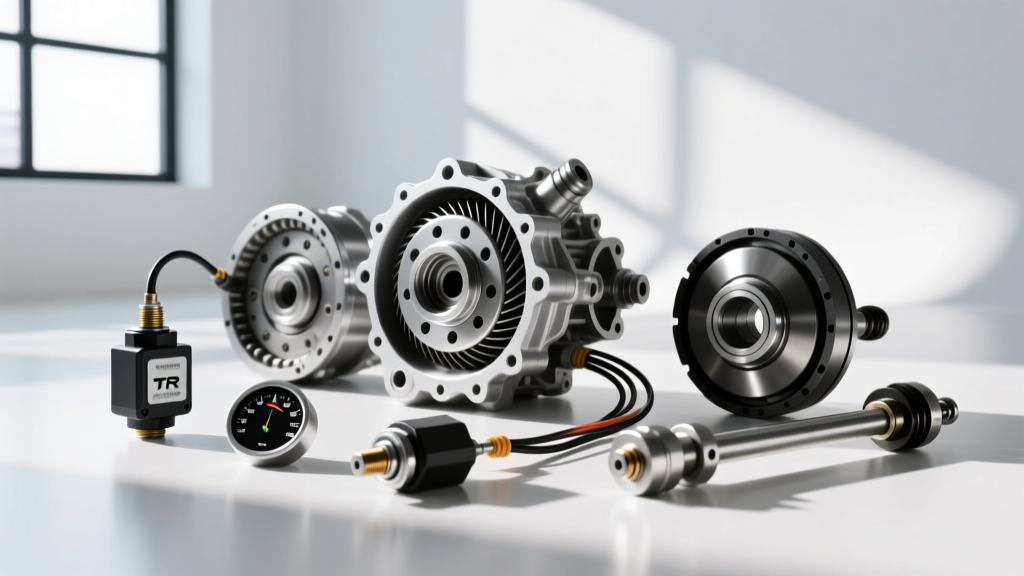
When enthusiasts, fleet managers, and performance tuners think of transmission electronic control systems, they immediately picture shift solenoids, input/output speed sensors, and the Transmission Control Module (TCM). However, one of the most critical components dictating transmission longevity and performance under heavy loads is located at the front of the engine: the fan clutch solenoid. In modern heavy-duty and high-performance applications—such as the GM Allison 1000, Ford 6R140, and even the ZF 8HP in commercial tow rigs—the engine's electro-viscous fan clutch is directly integrated into the powertrain's thermal management strategy.
Upgrading and recalibrating the fan clutch solenoid is a premier performance modification for 2026 that prevents transmission fluid degradation, maintains optimal torque converter clutch (TCC) lockup, and averts catastrophic thermal limp modes. By bridging the gap between engine cooling and transmission electronic control systems, you can unlock a new tier of towing reliability and track-day endurance.
How the TCM and PCM Collaborate on Thermal Management
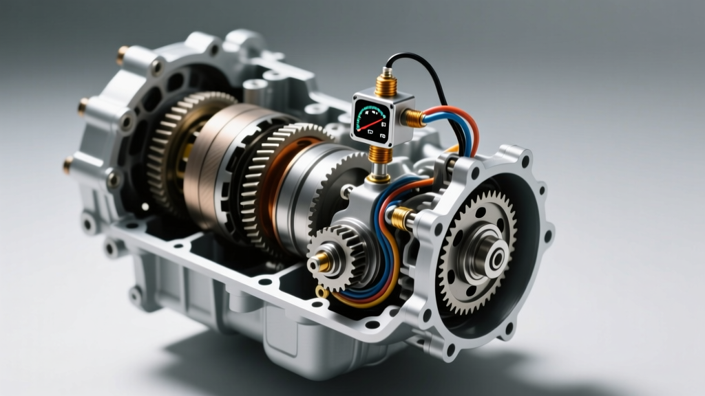
The Transmission Fluid Temperature (TFT) sensor is a vital thermistor located within the transmission pan, valve body, or integrated mechatronics unit. As fluid temperatures climb past 200°F (93°C), the TCM begins altering shift pressures and timing to reduce internal friction. If temperatures breach 250°F (121°C), the TCM commands a defuel strategy and forces the torque converter to unlock, which paradoxically generates even more heat due to fluid shear.
To prevent this thermal runaway, the TCM sends a high-priority CAN bus request to the Powertrain Control Module (PCM). The PCM then adjusts the Pulse Width Modulation (PWM) signal sent to the fan clutch solenoid. This solenoid regulates hydraulic fluid flow inside the viscous fan clutch hub, dictating fan RPM and, consequently, the airflow across the transmission cooler. A sluggish, restrictive, or factory-limited solenoid creates a dangerous thermal bottleneck that no aftermarket transmission cooler can overcome on its own.
Upgrading the Fan Clutch Solenoid for Heavy-Duty Performance
Factory fan clutch solenoids are calibrated primarily for NVH (Noise, Vibration, and Harshness) and corporate fuel economy standards, not maximum towing performance. The OEM PWM duty cycle often delays full fan engagement until the engine coolant temperature (ECT) is critical, ignoring the TFT sensor's warnings until the transmission is already in danger. Performance upgrades focus on two distinct areas: hardware response time and software recalibration.
Hardware: High-Flow PWM Solenoid Valves
Upgrading to a high-flow solenoid valve assembly reduces the hydraulic lag inside the fan clutch hub. For GM Duramax applications utilizing the Allison 1000, replacing the restrictive OEM valve with a high-performance aftermarket unit allows the viscous silicone fluid to transfer torque to the fan blade assembly up to 40% faster. This rapid engagement ensures that when the TCM detects a 10°F spike in transmission fluid temperature during a steep grade climb, the cooling airflow is maximized within milliseconds, not seconds.
| Feature | OEM Fan Clutch Solenoid | Performance PWM Upgrade |
|---|---|---|
| Hydraulic Response Time | 1.2 - 1.8 Seconds | 0.4 - 0.7 Seconds |
| Max Duty Cycle Flow Rate | Restricted for NVH | Unrestricted High-Flow |
| PWM Frequency Tolerance | 100Hz - 200Hz | 100Hz - 500Hz+ |
| Estimated Cost (2026) | $85 - $140 | $180 - $275 |
Recalibrating Transmission Electronic Control Systems
Hardware is only half the battle. To truly leverage a performance fan clutch solenoid, you must reprogram the PCM and TCM thermal tables using advanced tuning software like HP Tuners MPVI3 or EFI Live. By accessing the 'Fan Desired Speed vs. TFT' tables, tuners can completely rewrite the thermal logic to prioritize transmission survival over cabin quietness.
Custom Tuning Strategies for TFT Integration
- Early Engagement Thresholds: Factory tables often command 100% fan clutch solenoid duty cycle only when the TFT reaches 235°F (112°C). Performance tuning shifts this curve, commanding 80% duty cycle at just 185°F (85°C), keeping the fluid in the optimal viscosity window for the TCC friction material.
- Decoupling ECT and TFT Logic: In many OEM setups, if the engine coolant is cool, the PCM will override the TCM's request for fan speed to save fuel. Custom tuning forces the PCM to honor the TFT sensor's CAN bus requests regardless of ECT, ensuring the transmission cooler receives airflow even during cold-weather heavy towing.
- TCC Lockup Preservation: By maintaining lower TFTs via the upgraded solenoid, the TCM will maintain torque converter lockup in lower gears, reducing slip and drastically improving both fuel economy and transmission lifespan.
Expert Insight: According to thermal management analyses published by Transmission Digest, maintaining TFT below 210°F (98°C) can extend the life of synthetic ATF and clutch friction materials by up to 300% under continuous heavy-load conditions.
Wiring Harness and Electrical Integrity Upgrades
When commanding higher, more aggressive PWM duty cycles to the fan clutch solenoid, the factory wiring harness can become a liability. Voltage drop across long, thin OEM wires can result in the solenoid receiving only 10.5V instead of the required 12V, leading to incomplete hydraulic valve actuation. For severe-duty applications, building a dedicated relay-driven PWM harness using 12 AWG silicone-insulated wiring and Delphi Metri-Pack 280 series terminals is highly recommended. This ensures the solenoid receives a crisp, uncorrupted signal, a principle heavily emphasized in advanced electronics diagnostics by Sonnax Tech Resources.
Diagnostic Trouble Codes (DTCs) to Monitor
When modifying transmission electronic control systems and cooling circuits, you must monitor specific OBD-II codes. A failing or improperly tuned fan clutch solenoid will quickly trigger a cascade of transmission and engine codes:
- P0480 (Fan Control Circuit 1 Malfunction): Often caused by voltage drop in the PWM control wire or a shorted solenoid coil. If the PCM cannot verify the solenoid's electrical feedback, it will default the fan to a mechanical limp mode.
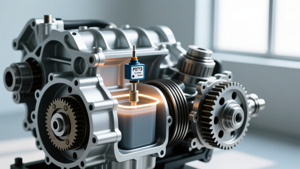
- P0711 (TFT Sensor Circuit Range/Performance): If the upgraded solenoid engages too aggressively, it can cause rapid, erratic drops in fluid temperature that the TCM interprets as a faulty thermistor.
- P0741 (Torque Converter Clutch Circuit Performance/Stuck Off): A secondary code triggered when the TCM commands TCC lockup, but excessive heat (due to poor solenoid performance) causes the clutch to slip, registering a speed differential between the input and output speed sensors.
Installation and Torque Specifications
Installing an upgraded fan clutch solenoid requires precision. The solenoid is typically mounted directly to the fan clutch hub or the engine front cover, depending on the architecture. When servicing the electro-viscous assembly on a GM 6.6L Duramax or Ford 6.7L PowerStroke, cleanliness is paramount. Any debris entering the hydraulic reservoir will jam the solenoid's internal spool valve.
Critical Installation Steps
1. Electrical Disconnect: Always isolate the negative battery terminal to prevent accidental PWM signal spikes that can fry the PCM driver circuit.
2. Thread Sealant: If the solenoid threads directly into the fluid reservoir, apply a medium-strength thread sealant rated for silicone-based viscous fluids. Do not use standard Teflon tape, which can shred and block the hydraulic metering orifices.
3. Torque Specifications: Solenoid retaining bolts are typically small and prone to stripping. Adhere strictly to the OEM torque specification, usually between 8 Nm and 12 Nm (71 to 106 lb-in). Over-torquing will warp the solenoid housing and bind the internal plunger.
4. Dielectric Grease: Pack the PWM electrical connector with a high-temp dielectric grease to prevent moisture intrusion, which is the leading cause of PWM signal degradation in heavy-duty towing environments.
By treating the fan clutch solenoid as an integral component of your transmission electronic control system, rather than just an engine accessory, you unlock a level of thermal stability that bolt-on coolers alone cannot achieve. Whether you are pushing a ZF 8HP on a road course or towing 20,000 lbs with an Allison 1000, mastering PWM thermal management is the ultimate performance upgrade.