The Anatomy of Transmission Limp Mode
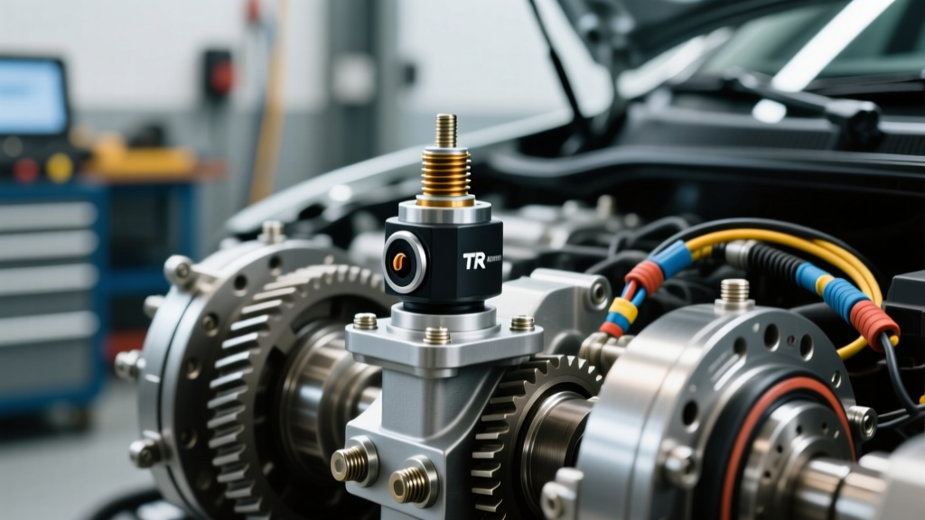
When your vehicle’s Transmission Control Module (TCM) detects a critical fault that could damage the drivetrain or compromise safety, it triggers a failsafe state commonly known as 'limp mode' or 'limp-home mode.' In this state, the TCM typically locks the transmission into a single gear (often 3rd gear) and restricts engine RPM to prevent catastrophic mechanical failure. While low fluid levels, failed shift solenoids, or damaged speed sensors can trigger this failsafe, one of the most frequent culprits is a faulty Transmission Range (TR) sensor, also known as the transmission position sensor or Internal Mode Switch (IMS).
If your vehicle is stuck in limp mode and throwing codes in the P0705 to P0708 range, a transmission position sensor replacement might be the exact fix you need. However, blindly swapping parts without proper diagnosis is a costly mistake. This step-by-step guide will walk you through professional limp mode diagnosis, electrical verification, and the precise replacement procedures for common platforms like the GM 6L80 and Ford 6R80.
Step 1: Interrogate the TCM and Isolate the Circuit
The first step in any transmission limp mode diagnosis is pulling the Diagnostic Trouble Codes (DTCs) with a bidirectional OBD2 scanner. You must differentiate between a mechanical linkage issue, a wiring harness fault, and an internal sensor failure. According to the OBD-Codes P0705 Guide, the TCM monitors the voltage signals from the position sensor to determine the exact gear selector position. If the signals contradict each other or drop out entirely, the TCM defaults to limp mode.
Common Position Sensor DTCs
| DTC | Description | Primary Symptom | Diagnostic Focus |
|---|---|---|---|
| P0705 | Transmission Range Sensor Circuit Malfunction | Limp mode, no-start condition, reverse lights stuck on | 5V Reference circuit, Ground circuit |
| P0706 | Transmission Range Sensor Circuit Range/Performance | Erratic shifting, TCM cannot identify 'Park' or 'Neutral' | Sensor alignment, mechanical linkage binding |
| P0707 | Transmission Range Sensor Circuit Low Input | Vehicle stuck in single gear, check engine light | Short to ground on signal wires |
| P0708 | Transmission Range Sensor Circuit High Input | No crank/no start, TCM failsafe triggered | Open circuit, short to voltage, corroded connector |
Step 2: Electrical Verification vs. Mechanical Binding
Before ordering parts for a transmission position sensor replacement, you must rule out external factors. The TR sensor relies on a 5-volt reference signal from the TCM, a low-reference (ground), and typically four discrete signal wires (Signal A, B, C, and P). These signals create a binary 'Grey Code' pattern that tells the TCM exactly where the manual shaft is positioned.
- Check the Linkage: Crawl under the vehicle and have an assistant move the shifter through all gears while you watch the transmission manual shaft lever. If the cable is stretched or the bushing is degraded, the lever won't travel fully into the detents, causing a P0706 code even if the sensor is perfectly healthy.
- Monitor Live Data: Connect your bidirectional scanner and navigate to the TCM live data stream. Look for the 'Gear Position' or 'PRNDL State' PID. As you move the shifter, the PID should snap crisply from P to R to N to D. If the PID shows 'Undefined' or 'Error' in specific positions, you have isolated the fault to the sensor or its immediate wiring.
- Multimeter Testing: Back-probe the sensor connector. Verify that you have exactly 4.8V to 5.1V on the reference wire with the key on, engine off (KOEO). If the 5V reference is missing, trace the wiring back to the TCM before condemning the sensor.
Step 3: Transmission Position Sensor Replacement Procedures
Once electrical and mechanical linkage issues are ruled out, it is time to proceed with the transmission position sensor replacement. The procedure varies wildly depending on whether your transmission uses an external TR sensor or an internal mode switch.
Scenario A: External TR Sensor (Ford 6R80 / ZF 6HP)
On the Ford 6R80 and many ZF 6HP applications, the TR sensor is mounted externally on the side of the transmission case, directly over the manual shaft lever. This makes replacement relatively straightforward, though it requires working underneath the vehicle.
- Preparation: Disconnect the negative battery terminal. Safely raise and support the vehicle on jack stands. Remove any heat shields or exhaust components blocking access to the driver’s side of the transmission case.
- Removal: Disconnect the electrical harness connector from the TR sensor. Remove the manual shaft lever nut (typically 15mm or 16mm) and slide the lever off the splined shaft. Remove the two TR sensor mounting bolts.
- Alignment (CRITICAL): The new sensor must be installed in the exact Neutral position. Most OEM sensors feature alignment marks—two lines or dots on the sensor body that must perfectly match up when the manual shaft is in Neutral. Use a 2mm alignment pin or drill bit through the alignment holes to lock the sensor in place during installation.
- Torque Specifications: Install the new sensor and torque the mounting bolts to 89 lb-in (10 Nm). Reinstall the manual shaft lever and torque the retaining nut to 22 lb-ft (30 Nm). Remove the alignment pin before reconnecting the battery.
Scenario B: Internal Mode Switch (GM 6L80 / 8L90)
General Motors’ 6L80 and 8L90 transmissions utilize an Internal Mode Switch (IMS) located inside the transmission pan. A transmission position sensor replacement on these units is significantly more invasive, requiring a fluid drain and pan removal. As detailed in professional repair databases like YourMechanic's TR Sensor Replacement Guide, cleanliness is paramount when opening the transmission sump.
- Fluid Drain & Pan Removal: Drain the transmission fluid (expect roughly 6.3 quarts of Dexron VI to drain from the pan). Remove the 18 pan bolts (8mm heads). Carefully lower the pan and remove the old filter.
- Valve Body Access: Disconnect the main internal wiring harness connector from the valve body. You will need to unbolt the IMS wiring harness bracket. The IMS is located near the manual shaft detent lever.
- IMS Removal: Unclip the shift linkage from the manual shaft detent lever. Remove the three IMS retaining bolts. Slide the old IMS off the manual shaft.
- Installation & Alignment: The GM IMS also requires Neutral alignment. Ensure the transmission manual shaft is in the Neutral detent. Align the tabs on the new IMS with the flats on the manual shaft. The alignment marks on the sensor body must line up perfectly.
- Torque Specifications: Torque the IMS retaining bolts to 97 lb-in (11 Nm). Reconnect the shift linkage and torque the harness bracket bolts to 71 lb-in (8 Nm). Install a new transmission filter and use a new OEM pan gasket. Torque the pan bolts in a crisscross pattern to 71 lb-in (8 Nm).
Expert Technician Tip: Never use RTV silicone on the GM 6L80 transmission pan unless explicitly specified by an updated TSB. The OEM molded rubber gasket is designed to seal without sealant. RTV can easily break off, enter the pickup tube, and starve the transmission of oil pressure, causing a far worse failure than the original limp mode.
Step 4: TCM Relearn and Calibration
The physical transmission position sensor replacement is only half the battle. Once the new sensor is installed and the battery is reconnected, the TCM must learn the new sensor's voltage parameters. On modern vehicles, simply clearing the codes is not enough.
Connect your bidirectional scanner and perform a 'TCM Adapt Reset' or 'Shift Adapt Relearn.' Cycle the ignition to the 'Run' position (without starting the engine), press the brake pedal, and slowly move the shifter through every gear position, pausing for two seconds in each detent. This allows the TCM to map the new voltage thresholds for Park, Reverse, Neutral, Drive, and Low. Finally, clear all stored DTCs and perform a 15-mile test drive to ensure the transmission shifts crisply and the limp mode failsafe does not return.
Cost Breakdown and OEM Part Numbers
When performing a transmission position sensor replacement, always opt for OEM or premium Tier-1 supplier parts. Cheap aftermarket sensors often suffer from poor internal potentiometer tolerances, leading to recurring P0706 codes within a few thousand miles.
- GM 6L80 / 6L90 Internal Mode Switch: ACDelco Part #24252835. Retail price ranges from $140 to $180.
- Ford 6R80 External TR Sensor: Motorcraft Part #SW-6857. Retail price ranges from $65 to $95.
- ZF 6HP TR Sensor (BMW/Audi applications): Often integrated into the Mechatronic unit or sold as a standalone ZF-branded unit (Part #0501-216-243). Price ranges from $120 to $220.
- Consumables: Budget an additional $40-$70 for OEM transmission fluid, a new filter, and a pan gasket if working on an internal IMS setup.
By following this methodical limp mode diagnosis and adhering to strict torque and alignment specifications, you can confidently resolve transmission failsafe codes and restore full drivability without resorting to unnecessary transmission rebuilds or TCM replacements.