Understanding the Torque Converter in CVT Transmissions
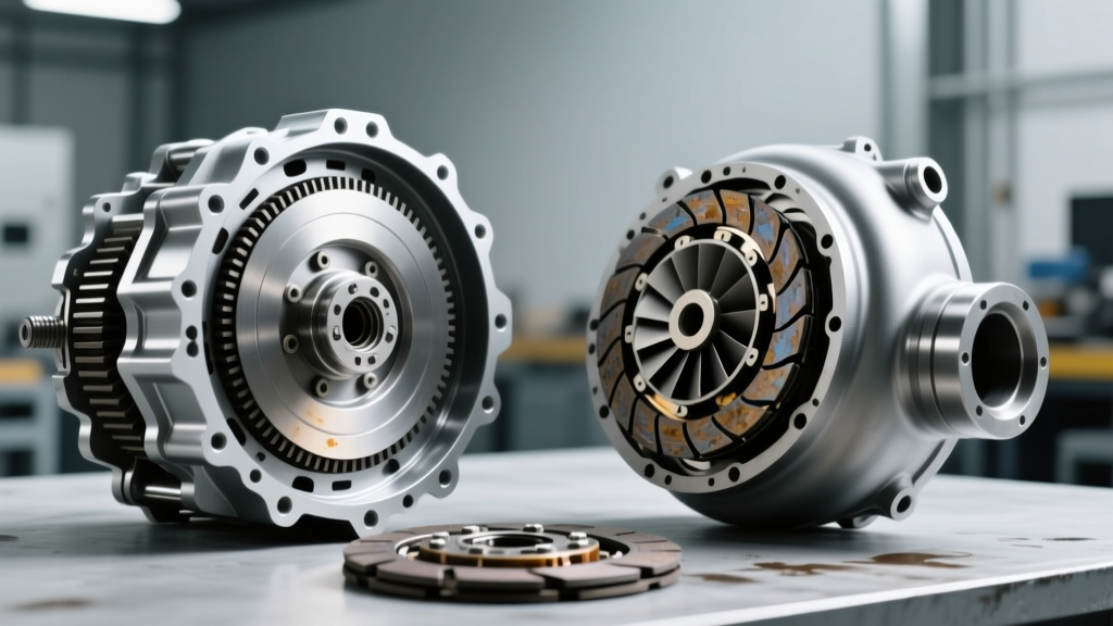
While Continuously Variable Transmissions (CVTs) rely on steel belts and variable-diameter pulleys to provide infinite gear ratios, they still utilize a traditional fluid coupling at the engine's output: the torque converter. In modern CVT designs—such as the Jatco JF011E (found in Nissan and Jeep models), the Subaru Lineartronic TR690, and the Toyota Direct Shift-CVT (K120)—the torque converter is equipped with a highly sophisticated lockup clutch. Unlike older stepped automatics that only lock up at highway speeds, modern CVTs engage the torque converter clutch (TCC) as early as 15 to 20 mph to eliminate slippage, reduce heat generation, and improve fuel economy.
When technicians or DIYers refer to the torque converter lockup switch in a CVT, they are typically referring to the TCC pressure switch, the lockup control solenoid feedback circuit, or the TCM's internal monitoring logic that verifies clutch engagement. A failure in this circuit results in severe shudder, RPM flares, overheating, and eventual belt slip. This step-by-step guide will walk you through diagnosing the lockup mechanism in a CVT environment with precision.
Step 1: TCM Live Data Analysis (The Digital Test)
Before dropping a transmission pan or breaking out a multimeter, you must interrogate the Transmission Control Module (TCM). CVT lockup clutches operate on Pulse Width Modulation (PWM) and require precise slip control. You will need an advanced bi-directional scan tool (e.g., Autel MaxiSys MS908S or Snap-on Zeus) capable of reading OEM-specific CVT PIDs.
Key PIDs to Monitor:
- TCC Slip Speed: Monitor the difference between engine RPM and transmission input shaft speed. During steady-state cruising (40-50 mph), slip should be between -20 and +20 RPM. If slip exceeds 100 RPM while the TCM commands lockup, the clutch is failing to apply, or the hydraulic switch circuit is misreporting pressure.
- Lockup Solenoid Duty Cycle: Expressed as a percentage. A commanded duty cycle of 85-95% typically indicates full lockup apply. If the TCM commands 90% but slip remains high, you have a hydraulic or mechanical failure.
- TCC Pressure Switch State: Some CVTs utilize a discrete pressure switch to verify that hydraulic fluid has crossed the lockup apply circuit. If the scan tool shows 'OFF' despite high solenoid duty cycle, the switch, the valve body separator plate, or the solenoid itself has failed.
Expert Insight: According to SAE International technical papers on CVT slip-control algorithms, the TCM constantly adapts the PWM duty cycle based on fluid temperature and clutch wear. If your scan tool shows 'Adaptation Limit Reached' for the TCC, the physical friction material inside the torque converter is worn out, and no electrical switch replacement will fix the shudder.
Step 2: Electrical Pinout and Resistance Testing
If the scan tool points to an electrical fault (common DTCs include P0740, P0741, P2764), the next step is to test the physical circuit. In most CVTs, the lockup solenoid and its associated monitoring switch are integrated into the valve body solenoid pack, accessible by dropping the transmission fluid pan.
Testing the Jatco JF011E (RE0F10A) Lockup Solenoid:
- Safety First: Disconnect the negative battery terminal. Raise the vehicle and drain the CVT fluid into a clean catch pan (approx. 4.5 liters for a standard drain and fill).
- Remove the Pan: Remove the 18 pan bolts (10mm heads). Torque spec for reinstallation is 6 Nm (53 in-lbs). Clean the magnets; excessive clutch material indicates internal TCC destruction.
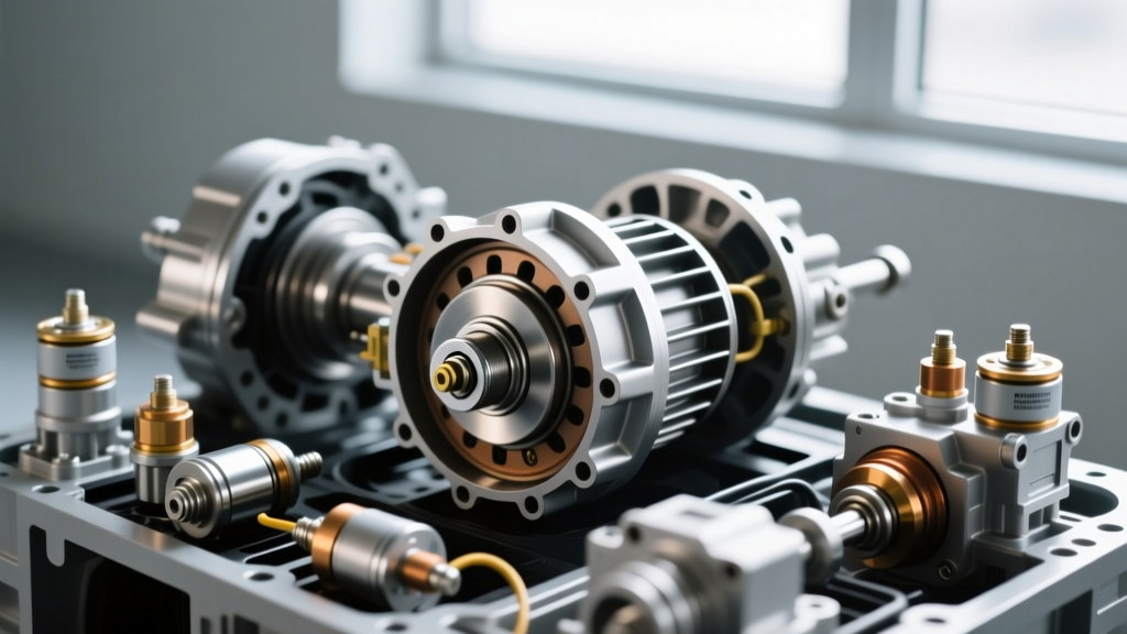
- Locate the Solenoid Pack: The lockup solenoid is typically a brown or black cylindrical component on the valve body.
- Multimeter Test: Set your digital multimeter to Ohms (Ω). Back-probe the lockup solenoid pins at the main transmission case connector (often Pin 14 and Pin 15, depending on the exact Nissan/Jeep wiring diagram). The expected resistance for the JF011E lockup solenoid at 20°C (68°F) is 11 to 15 Ohms.
- Switch Continuity: If your specific CVT variant uses a discrete TCC pressure switch mounted on the case, test for continuity. The switch should be 'Open' (OL) with no fluid pressure and 'Closed' (near 0 Ohms) when shop air (approx. 50 PSI) is applied to the lockup apply port.
Step 3: Hydraulic Lockup Pressure Verification
Electrical tests only confirm that the wiring and coils are intact. They do not confirm that the valve body is routing fluid or that the torque converter lockup switch is accurately reading hydraulic pressure. For this, you need a transmission pressure gauge kit (0-300 PSI).
- Locate the TCC Apply Port: On the Subaru Lineartronic TR690, the lockup apply pressure port is located on the top of the transmission case near the bellhousing. On the Toyota K120, it is integrated into the main pressure test block on the side of the case.
- Connect the Gauge: Thread the appropriate adapter into the TCC apply port and route the hose safely to the windshield.
- Road Test: Drive the vehicle until the CVT fluid reaches operating temperature (50°C - 80°C). Maintain a steady 45 mph on a flat surface.
- Read the Pressure: When the TCM commands lockup, the TCC apply pressure should spike from a baseline of 15-25 PSI up to 110-140 PSI. If the pressure remains low despite a high solenoid duty cycle command, the lockup control valve in the valve body is stuck, or the separator plate gaskets are blown.
CVT Lockup Component Replacement & Specifications
If your diagnosis confirms a failed lockup solenoid, a stuck pressure switch, or a worn torque converter clutch, replacement is mandatory. Ignoring CVT lockup shudder will rapidly degrade the steel push-belt, leading to a catastrophic $4,500+ transmission replacement.
Cost and Parts Breakdown (2026 Estimates)
| Component / Service | Part Number / Spec | Estimated Cost (USD) |
|---|---|---|
| Jatco JF011E Solenoid Pack (OEM) | Nissan 31705-1XF0A | $280 - $350 |
| Subaru TR690 Lockup Solenoid | Subaru 31773AA040 | $140 - $190 |
| Remanufactured CVT Torque Converter | Vehicle Specific (e.g., Jasper) | $450 - $700 |
| Valve Body Assembly (Complete) | OEM / Rostra | $500 - $950 |
| Labor (Pan Drop & Solenoid Swap) | 2.5 - 3.5 Hours | $350 - $550 |
Critical Torque Specs and Fluid Requirements
When reassembling the CVT after testing the lockup switch or replacing the solenoid pack, precision is vital. CVT valve bodies are highly sensitive to warping and cross-leaks.
- Valve Body to Case Bolts (Jatco JF011E): 8 Nm (71 in-lbs). Do not overtighten; the aluminum case threads strip easily.
- CVT Fluid Selection: You MUST use the exact OEM-specified fluid. Using generic 'Universal CVT' fluid will alter the friction coefficient of the lockup clutch, causing immediate shudder. Use Nissan NS-3, Subaru Lineartronic CVTF-II, or Toyota CVTF-FE.
- Fluid Level Check: CVTs do not have traditional dipsticks. The fluid level must be checked via the overflow plug on the pan while the fluid temperature is exactly 40°C (104°F), monitored via the scan tool's 'CVT Fluid Temp' PID.
Common CVT Lockup Fault Codes Reference
| OBD-II DTC | Description | Primary CVT Culprit |
|---|---|---|
| P0740 | TCC Solenoid Circuit Malfunction | Open/Short in wiring harness or burnt solenoid coil. |
| P0741 | TCC System Stuck Off | Failed lockup switch, stuck valve, or low line pressure. |
| P0742 | TCC System Stuck On | Debris in valve body locking the apply valve; engine will stall at stops. |
| P2764 | TCC Solenoid Control Circuit Low | Short to ground in the TCM driver circuit or internal TCM failure. |
Final Diagnostic Verdict
Diagnosing a torque converter lockup switch or solenoid in a CVT requires moving beyond simple electrical tests. Because CVTs rely on the lockup clutch for primary efficiency and thermal management, the TCM's adaptive learning strategies can mask early mechanical wear. Always pair your multimeter resistance tests with live-data slip analysis and hydraulic pressure verification. For further reading on CVT hydraulic circuit design and slip-control methodologies, refer to the technical archives at Wikipedia's CVT Engineering Overview and OEM service bulletins. By following this systematic approach, you can accurately isolate whether the fault lies in the electrical switch, the hydraulic valve body, or the torque converter itself, saving thousands in unnecessary parts replacement.