The Critical Role of the TCC Solenoid in Modern Drivetrains
The Torque Converter Clutch (TCC) solenoid is the vital electro-hydraulic bridge between the Transmission Control Module (TCM) and the physical lockup clutch inside the torque converter. When functioning correctly, it modulates hydraulic pressure to apply the TCC, eliminating slip between the engine and transmission at cruising speeds to maximize fuel economy and reduce heat. However, TCC solenoid problems remain one of the most frequent culprits behind diagnostic trouble codes (DTCs) like P0741 (TCC Stuck Off), P0742 (TCC Stuck On), and P0744 (TCC Circuit Intermittent).
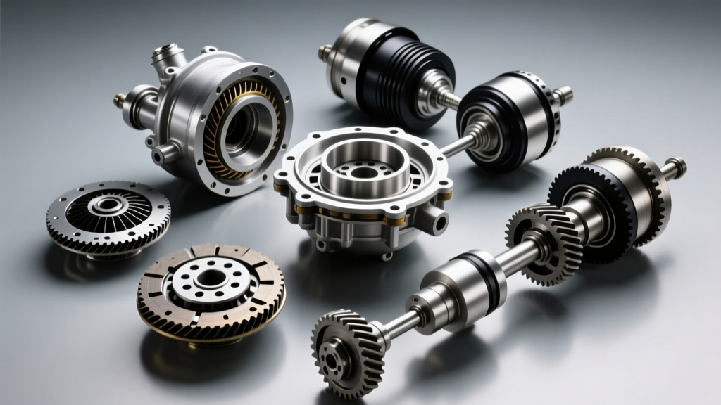
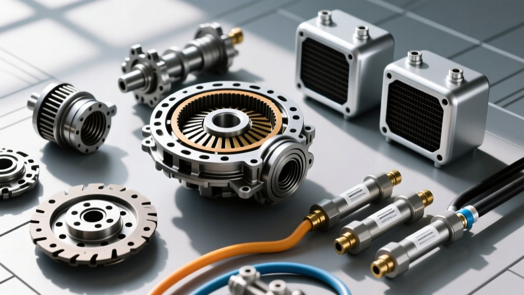
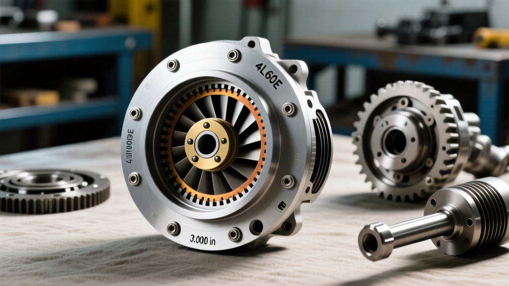
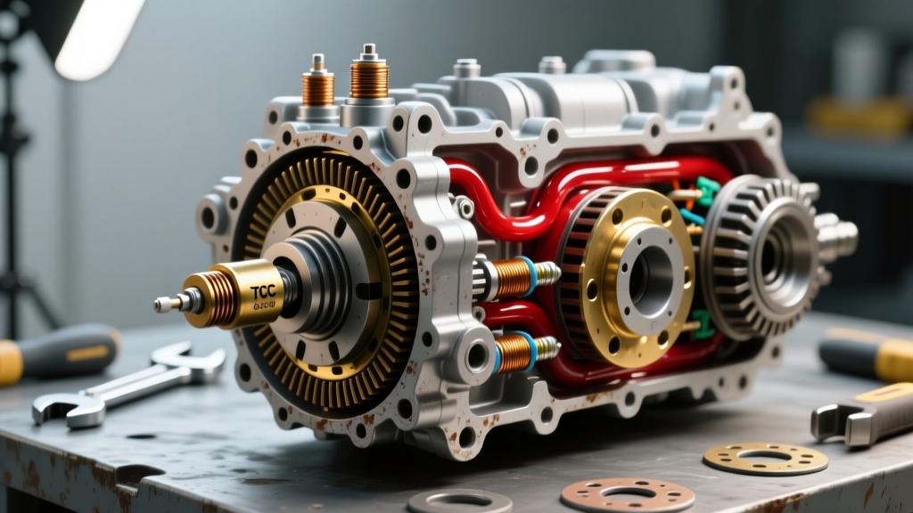
As an automotive transmission specialist, diagnosing these issues requires more than just plugging in an OBD2 scanner. It requires a deep understanding of hydraulic circuits, electrical resistance parameters, and physical debris analysis. In advanced transmission rebuilding seminars, analyzing high-resolution torque converter pictures of sectioned units is a standard best practice. These visual forensics reveal the root causes of solenoid failure—such as clutch lining degradation, varnish buildup, or catastrophic bearing wear—that a simple code reader will never show you.
Visual Forensics: What Torque Converter Pictures Reveal
Before dropping a valve body or replacing a mechatronic unit, expert technicians look at the physical evidence left behind in the transmission fluid and the converter itself. When reviewing torque converter pictures from cut-open failed units, three distinct visual clues point directly to TCC solenoid and hydraulic circuit distress:
- Friction Material Suspensions: If the transmission pan contains a fine, glitter-like silt (often mistaken for metallic wear), it is usually degraded TCC friction material. This silt bypasses the filter and lodges directly inside the TCC solenoid's micro-screen or spool valve, causing it to stick.
- Blued Steel and Thermal Scoring: Visual inspections showing blued or heat-scoring marks on the converter's inner clutch surface indicate prolonged TCC slip. This is often caused by a solenoid failing to deliver adequate apply pressure, forcing the TCM to continuously pulse the clutch in a vain attempt to achieve lockup.
- Varnish and Sludge Accumulation: In neglected units, oxidized fluid forms a hard varnish. This varnish coats the solenoid armature, increasing electrical resistance and slowing the hydraulic response time, triggering intermittent shudder codes.
Expert Insight: Never replace a TCC solenoid without inspecting the transmission pan and, if possible, reviewing borescope or cutaway torque converter pictures of similar failed units. If the converter is shedding heavy friction material, replacing the solenoid without flushing or replacing the torque converter will result in a repeat failure within 500 miles.
Platform-Specific Diagnostics & Best Practices
TCC solenoid architecture varies wildly across different transmission families. Below is a deep dive into three of the most common platforms seen in repair bays today, complete with exact specifications and diagnostic procedures.
1. GM 4L60E: The PWM Solenoid Era
The 4L60E utilizes a dedicated Pulse Width Modulated (PWM) TCC solenoid to allow for controlled, smooth lockup apply. The solenoid is mounted directly on the valve body.
- OEM Part Number: AC Delco 214-1893 (GM 24212690)
- Resistance Specification: 10.0 to 15.0 Ohms at 68°F (20°C)
- Common Failure Mode: The internal coil winding shorts out due to heat, or the exhaust ball becomes trapped by debris, leading to a P0742 (TCC Stuck On) which can stall the engine when coming to a stop.
- Best Practice: Always test the solenoid with a digital multimeter (DMM) at the transmission harness connector (Pin A to Pin E) before removing the pan. If resistance is out of spec, the solenoid must be replaced. Furthermore, inspect the TCC regulator valve bore in the valve body for wear, a known issue extensively documented by Sonnax technical resources.
2. GM 6L80 / 6L90: TEHCM Integration
In the 6-speed 6L80, the TCC solenoid is no longer a standalone component. It is integrated directly into the Transmission Electro-Hydraulic Control Module (TEHCM), which houses the TCM, solenoids, and pressure switches inside the transmission pan.
- OEM Part Number: GM 24239178 (TEHCM Assembly)
- Resistance Specification: Internal testing requires a specialized breakout box; however, TCC solenoid internal resistance typically reads between 2.0 and 4.0 Ohms.
- Common Failure Mode: Micro-cracks in the TEHCM circuit board or internal solenoid screen clogging from clutch debris.
- Best Practice: You cannot replace just the TCC solenoid on a 6L80. The entire TEHCM must be replaced. Critical: The new TEHCM requires programming and a Service Fast Learn adaptation process using GM's Techline Connect (TLC) software. Failing to program the unit will result in immediate harsh shifts and TCC shudder.
3. ZF 8HP (8-Speed): Mechatronic Precision
The legendary ZF 8HP series uses a Mechatronic unit where the TCC apply is managed by highly sensitive EDS (Electro-Pressure) solenoids. These solenoids operate on a variable pressure principle rather than simple on/off or standard PWM.
- OEM Part Number: ZF 1068.298.062 (Mechatronic Assembly - specific solenoids are sometimes serviceable separately depending on the exact sub-model and year).
- Resistance Specification: 5.0 to 5.6 Ohms at room temperature.
- Common Failure Mode: Electrical connector sleeve degradation (the famous ZF sleeve leak) allowing fluid to wick up into the TCM, causing solenoid communication faults.
- Best Practice: When diagnosing ZF TCC shudder, check the adapter plug sleeve for oil contamination. If oil is present in the TCM connector, the sleeve, bridge seal, and mechatronic sleeve must be replaced. Always use exact ZF LifeguardFluid 8 specifications; incorrect fluid friction modifiers will mimic a bad TCC solenoid.
Diagnostic Matrix: TCC Solenoid Symptoms vs. States
Use this matrix to cross-reference driver complaints with likely hydraulic/electrical solenoid states.
| Symptom / DTC | Probable Solenoid State | Hydraulic Result | Expert Action Plan |
|---|---|---|---|
| P0741 (TCC Stuck Off) | Open circuit or blocked supply | No lockup apply; high slip RPM | Check wiring harness, solenoid screen, and TCC apply valve. |
| P0742 (TCC Stuck On) | Shorted / mechanically jammed closed | Constant lockup; engine stalls at stop | Inspect exhaust orifice; replace solenoid; check for valve bore wear. |
| TCC Shudder (45-55 MPH) | Erratic PWM modulation | Rapid apply/release cycling | Verify fluid friction modifiers; test solenoid response with oscilloscope. |
| Harsh Lockup Engagement | Stuck high-pressure / Failed accumulator | Sudden, unmodulated hydraulic spike | Inspect TCC accumulator piston and springs; test solenoid PWM duty cycle. |
Step-by-Step Replacement & Torque Specifications
When electrical and visual diagnostics confirm a faulty TCC solenoid, precision during reassembly is non-negotiable. Improper torque on valve body or pan bolts will warp the casting, binding the very valves you are trying to fix. Below are the exact torque specifications for common platforms:
GM 4L60E Reassembly Specs
- Valve Body to Case Bolts: 97 lb-in (11 Nm). Do not over-torque; the aluminum case threads strip easily.
- TCC Solenoid Mounting Bracket: 89 lb-in (10 Nm).
- Transmission Pan Bolts: 106 lb-in (12 Nm).
- Fluid Requirement: Dexron VI (approx. 5-6 quarts for a pan drop and filter change).
GM 6L80 TEHCM Installation
- TEHCM to Case Bolts (M6): 89 lb-in (10 Nm).
- Filter to TEHCM Seal: Ensure the O-ring is fully seated and lubricated with clean Dexron VI before snapping the filter into the TEHCM.
- Fluid Requirement: Dexron VI (approx. 6-7 quarts).
Final Thoughts on Electrical Testing
While visual evidence from torque converter pictures and fluid analysis provides the 'why' behind a failure, the oscilloscope provides the 'how'. For intermittent TCC shudder complaints where resistance tests pass, hooking up a labscope to the TCC PWM circuit is the ultimate best practice. You are looking for a clean, square-wave pattern that modulates smoothly from 10% to 90% duty cycle as the TCM commands lockup. Any flat-lining, voltage spikes, or erratic duty cycle drops indicate either a failing TCM driver or a solenoid coil breaking down under thermal load.
By combining visual forensics, precise electrical testing, and strict adherence to OEM torque and programming specifications, you can eliminate TCC solenoid problems permanently, ensuring smooth, efficient lockup operation for the life of the transmission. For further reading on hydraulic valve body wear patterns, consult the International Automotive Technicians Network (iATN) transmission forums for real-world case studies from master rebuilders.