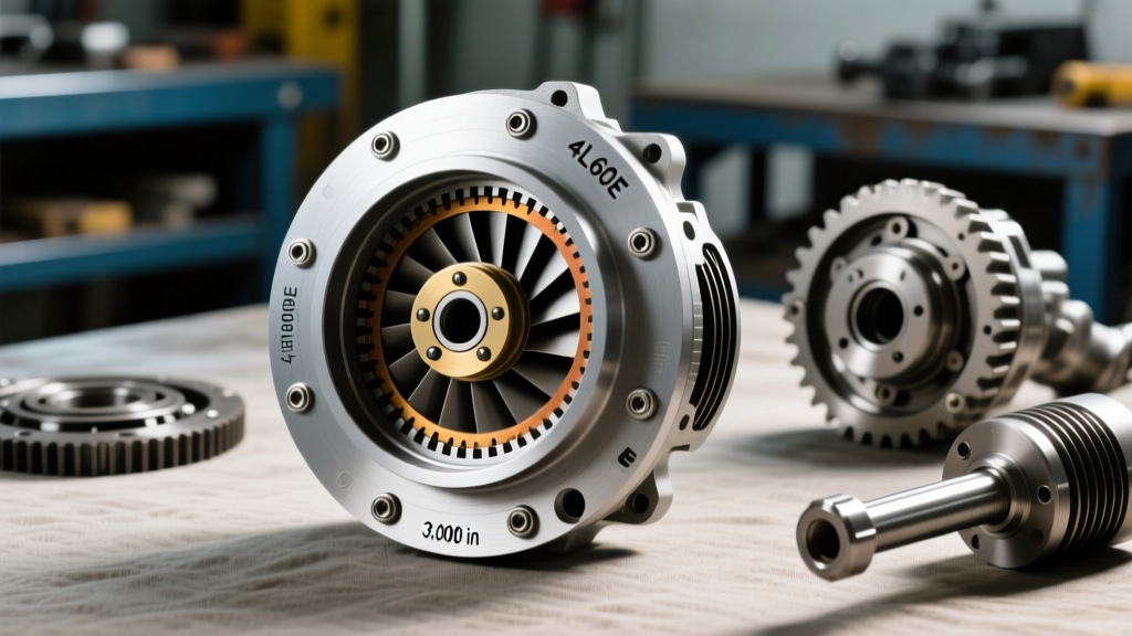
The Anatomy of a 4L60E 2500 Stall Converter Fitment
Upgrading to a performance torque converter is one of the most effective ways to unlock the potential of a GM powertrain. Specifically, a 4L60E torque converter 2500 stall setup represents the ultimate sweet spot for street-and-strip applications, offering a noticeable improvement in off-the-line torque multiplication without sacrificing highway drivability or generating excessive idle heat. Whether you are pairing this setup with a classic Gen I Small Block Chevy, an LT1, or a modern LS-series engine, the hydraulic performance of the stall speed is only half the battle. The mechanical interface between the engine and the transmission is where builds either succeed or suffer catastrophic failure.
As automotive transmission specialists, we frequently diagnose front pump destruction, torque converter clutch (TCC) shudder, and flexplate fatigue that trace directly back to ignored fitment tolerances. This technical deep-dive explores the exact bolt patterns, pilot hub dimensions, and critical clearance protocols required to properly install and align a 2500-stall unit to the 4L60E platform.
Decoding the GM Torque Converter Bolt Pattern
Unlike Ford and Chrysler platforms that historically utilized 4-bolt torque converter patterns, the GM TH350, TH400, 700R4, and 4L60E family relies on a distinct 3-bolt configuration. Understanding the geometry of this pattern is mandatory when matching an aftermarket 2500-stall converter to your flexplate.
The 11 5/8" Bolt Circle Standard
The standard factory GM 4L60E torque converter pad features three mounting bosses arranged on an 11.625-inch (11 5/8") bolt circle. When sourcing a high-stall unit from manufacturers like Circle D Specialties or Vigilante, the converter pads will be pre-drilled to this exact specification. However, the aftermarket flexplate market often introduces variables. Many performance flexplates, such as those from TCI or B&M, feature dual-pattern drilling to accommodate both the standard 11 5/8" circle and the older, smaller 10.5-inch bolt circle found on some early metric GM applications. Always verify your flexplate drilling matches the 11.625" requirement before attempting to mate the components.
Attempting to force a misaligned bolt pattern or using elongated, worn-out mounting holes will result in uneven clamping force. This asymmetrical load transfers directly into the transmission’s front pump stator support, leading to premature bushing wear and eventual fluid leakage past the front seal.
Pilot Hub Sizing and Engine Block Alignment
The pilot hub is the machined snout protruding from the center of the torque converter. Its primary function is to center the converter within the engine’s crankshaft bore, ensuring absolute concentricity between the engine’s rotating assembly and the transmission’s input shaft and front pump gears. According to Sonnax Technical Resources, even a few thousandths of an inch in misalignment can cause the front pump gear set to bind, shatter, or gall the pump housing.
The 1.703" GM Specification
For the vast majority of GM V8 applications utilizing the 4L60E, the torque converter pilot hub outer diameter (OD) measures exactly 1.703 inches. The corresponding machined bore in the back of the engine’s crankshaft must be clean, free of rust, and measure between 1.703" and 1.705" to allow for a smooth, slip-fit insertion.
The LS-Swap Variable: When retrofitting a 4L60E torque converter 2500 stall unit behind an LS-series engine (e.g., LS1, LS3, LQ4), builders must exercise extreme caution. Early LS cranks feature a stepped pilot bore, and some aftermarket crankshafts or spacer rings alter the effective depth and diameter. If the 1.703" hub bottoms out against a shelf inside the crank bore before the converter pads seat against the flexplate, the transmission will be pushed rearward. This guarantees catastrophic failure of the front pump upon startup. Always perform a “clay test” or use a depth micrometer to verify crank bore clearance before final assembly.
Critical Clearance Measurements: The Pull-Forward Rule
Perhaps the most misunderstood aspect of drivetrain assembly is the converter-to-flexplate clearance, commonly referred to as the “pull-forward” measurement. The torque converter must be fully seated into the transmission—engaging the front pump drive tangs, the stator support splines, and the turbine shaft splines—before the transmission is bolted to the engine block.
Once the transmission is mated to the block, the flexplate should sit slightly behind the converter mounting pads. You must physically pull the flexplate forward to meet the converter pads. The ideal gap before pulling forward is between 1/8" (0.125") and 3/16" (0.187").
- Zero Clearance (Pre-loaded): If the flexplate touches the converter pads without being pulled forward, the converter is being forced outward. This will crush the front pump thrust washer, bind the pump gears, and likely snap the converter snout upon initial engine cranking.
- Excessive Clearance (> 1/4"): If you must pull the flexplate more than a quarter-inch to reach the bolts, tightening the nuts will permanently bow the flexplate toward the transmission. This causes severe TCC lockup shudder, erratic line pressures, and eventual flexplate cracking around the crank bolt circle.
For an in-depth look at how improper clearance affects hydraulic circuits, the TCI Automotive Tech Information library provides excellent hydraulic pressure schematics demonstrating how flexplate deflection alters internal valve body clearances.
4L60E 2500 Stall Fitment Specifications
Reference the table below to ensure your components meet the strict tolerances required for high-stall 4L60E applications.
| Parameter | Specification / Dimension | Critical Tolerance / Note |
|---|---|---|
| Bolt Pattern Circle | 11.625" (11 5/8") | Must match 3-bolt GM flexplate |
| Pilot Hub OD | 1.703" | Crank bore must be 1.703" - 1.705" |
| Pull-Forward Clearance | 0.125" to 0.187" | 1/8" to 3/16" gap required |
| Mounting Hardware | M10 x 1.5 Nuts (Grade 10.9) | ARP or OEM GM; no impact tools |
| Fastener Torque Spec | 35 - 45 lb-ft | Apply medium-strength threadlocker |
| Front Pump Tang Depth | 1.125" Minimum | Must fully engage pump drive gear |
Fastener Protocols and Torque Specifications
The hardware securing the torque converter to the flexplate endures immense shearing forces, especially during the violent torque multiplication phases of a 2500-stall launch. The factory GM 4L60E utilizes M10 x 1.5 metric nuts. Never use standard hardware store Grade 5 or Grade 8 zinc-plated nuts. You must use OEM GM replacement nuts, high-quality aftermarket equivalents, or specialized ARP fasteners rated for high-shear applications.
When installing the nuts, always thread them on by hand to prevent cross-threading the relatively soft welded nuts on the converter pad. Apply a medium-strength threadlocker (such as Loctite 243) to the threads to prevent backing out due to harmonic vibration. Torque the nuts in a star pattern to 38 lb-ft (the median of the 35-45 lb-ft GM specification). Never use an impact wrench to seat or tighten torque converter hardware. Impact guns introduce shock loads that can fracture the welded mounting pads on the converter cover, leading to catastrophic separation at high RPM.
Symptoms of Improper Fitment and Bolt Pattern Failure
Because this platform relies on precise hydraulic and mechanical alignment, deviating from the specifications above will manifest in distinct, often misdiagnosed drivetrain symptoms. Recognizing these early can save you from a complete transmission rebuild.
Front Pump Whine and Cavitation
If the pilot hub is slightly undersized, or if the crank bore is out-of-round, the converter will orbit rather than spin concentrically. This translates to a high-pitched whine that changes pitch with engine RPM, not vehicle speed. Over time, this eccentric rotation wallows out the front pump bushing, leading to a massive leak at the front seal and eventual pump gear shatter.
TCC Lockup Shudder and Slip
A flexplate that has been bowed forward due to excessive pull-forward clearance alters the axial position of the torque converter clutch (TCC) friction disc. When the PCM commands TCC lockup in 4th gear, the apply piston cannot fully stroke, or it applies at an severe angle. This results in the classic “driving over rumble strips” shudder sensation at highway speeds, a symptom frequently misdiagnosed as bad transmission fluid or a failing TCC solenoid. For more on diagnosing hydraulic versus mechanical shudder, consult the Summit Racing Torque Converter Installation Guide.
Delayed Engagement and Pump Gear Fracture
If the converter was not fully seated into the pump drive tangs before mating the transmission to the block, the rearward pressure will snap the cast-iron or powdered-metal inner pump gear the moment the engine fires. The immediate symptom is a complete lack of vehicle movement in all forward and reverse gears, accompanied by a loud, metallic crunching noise from the bellhousing area, followed by a pan full of cast-iron glitter.
Final Assembly Verification
Installing a 4L60E torque converter 2500 stall unit is a precision exercise that rewards patience and meticulous measurement. Before tightening a single bellhousing bolt, ensure the converter spins freely by hand, the pull-forward gap is verified with a straightedge and feeler gauge, and the pilot hub is lightly lubricated with assembly grease to prevent galling during initial startup. By respecting the 11 5/8" bolt circle, the 1.703" hub diameter, and the golden 1/8" clearance rule, your drivetrain will efficiently transfer power to the pavement for thousands of miles of reliable, high-performance operation.