The Physics of Performance Clutch Chatter
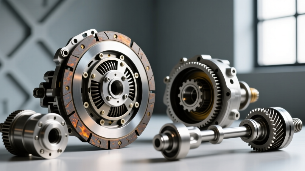
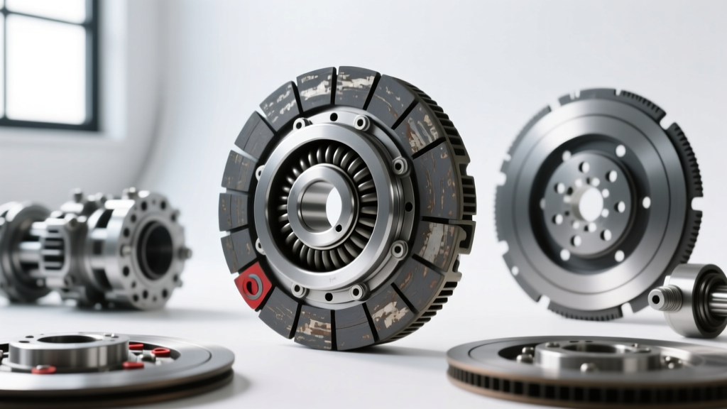
In the realm of high-horsepower manual swaps and track-focused builds, clutch chatter is more than a nuisance; it is a destructive harmonic feedback loop. When upgrading to aggressive friction materials like sintered iron or cerametallic compounds—such as those found in the RAM Clutches 900 Series or McLeod Street Twin assemblies—the coefficient of friction behaves differently than organic OEM materials. This creates a phenomenon known as stick-slip resonance. As the clutch engages, the friction material momentarily grabs, stops, and slips in rapid succession, transferring violent torsional oscillations through the transmission input shaft and into the chassis.
While amateur builders immediately blame the flywheel for hot spots or assume the friction disc is defective, seasoned drivetrain engineers know that the root cause often lies in the release geometry. Specifically, an improperly calibrated clutch adjuster—whether that is a mechanical pivot ball, an adjustable firewall cable quadrant, or a hydraulic master cylinder pushrod—forces the diaphragm spring to operate outside its optimal hysteresis window. In 2026, with the proliferation of high-torque LS, LT, and Coyote swaps utilizing Tremec T56 Magnum and TKX transmissions, understanding how your clutch adjuster dictates engagement smoothness is critical for both drivability and component survival.
Why Aggressive Friction Materials Expose Geometry Flaws
OEM organic clutches have a forgiving engagement curve. Performance clutches do not. If your clutch adjuster is set incorrectly, the release bearing may be pre-loading the diaphragm fingers at rest, or the geometric fulcrum point of the pressure plate is shifted. When the spring is over-centered or under-centered due to bad adjuster geometry, the clamping force fluctuates dynamically as the clutch engages. This fluctuating clamp load, paired with the aggressive bite of a sintered iron disc, guarantees severe vibration and chatter upon takeoff.
The Hidden Culprit: Clutch Adjuster Geometry
"Chatter is rarely a friction material defect in a fresh build; it is almost always a symptom of incorrect release bearing depth caused by a misadjusted clutch adjuster or incorrect bellhousing stack-up." — Driveline Integration Engineering Principles
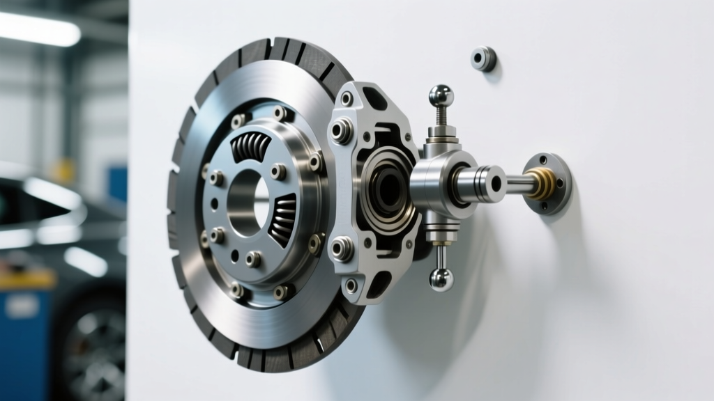
The term "clutch adjuster" encompasses several components depending on your platform. In a GM LS/T56 Magnum hydraulic setup, the adjuster is the master cylinder pushrod and the transmission pivot ball. In a Ford SN95 or Foxbody mechanical linkage, the adjuster is the firewall cable adjuster and aftermarket quadrant. In all cases, the adjuster's sole purpose is to dictate the resting position of the throwout bearing and the mechanical advantage applied to the diaphragm spring.
Mechanical vs. Hydraulic Adjuster Failure Modes
When diagnosing chatter, you must identify how your specific clutch adjuster is failing to maintain proper geometry:
- Hydraulic Pushrod Preload: If the master cylinder pushrod is adjusted too tightly (zero clearance), the hydraulic system cannot fully retract. This leaves the release bearing riding against the spinning diaphragm fingers, causing premature wear, harmonic vibration, and a slipping/chattering engagement as the clutch fails to fully clamp.
- Pivot Ball Height Deviation: In GM applications, adding a block plate or using an aftermarket SFI bellhousing (like a QuickTime RM-621) changes the bellhousing face-to-pivot-ball distance. If you do not use an adjustable clutch adjuster pivot ball to correct this, the release bearing will push the diaphragm spring past its dead-center point, resulting in violent chatter and incredibly high pedal effort.
- Cable Quadrant Slack: On Ford platforms, a worn or improperly adjusted firewall clutch adjuster allows the cable to stretch and snap during engagement, creating a shuddering vibration that mimics a warped flywheel.
Clutch Adjuster Upgrade & Torque Spec Matrix
To eliminate chatter, you must replace fixed, OEM-style adjusters with precision-machined aftermarket alternatives that allow for micro-calibration. Below is a diagnostic and upgrade matrix for the most common performance platforms.
| Platform | Adjuster Component | Recommended Part Number | Target Spec / Preload | Est. Cost (2026) |
|---|---|---|---|---|
| GM LS / T56 Magnum | Adjustable Pivot Ball | McLeod 169102 | 2.75" - 3.10" from bellhousing face | $85 - $110 |
| Ford SN95 / New Edge | Firewall Cable Adjuster | Maximum Motorsports MM53301 | 1/2" to 3/4" free play at lever | $65 - $80 |
| Universal Hydraulic | MC Pushrod Adjuster | Wilwood 260-1304 | 0.060" - 0.125" master cylinder gap | $42 - $55 |
| Ford Coyote / MT82 | Hydraulic Clutch Delay Valve Delete | Performance Friction 083.1410 | N/A (Removes artificial slip) | $35 - $50 |
Step-by-Step Chatter Diagnosis & Adjuster Calibration
If your performance build is suffering from takeoff shudder, follow this exact diagnostic sequence before pulling the transmission to resurface the flywheel. According to Tremec's official T56 Magnum installation guidelines, verifying external geometry is mandatory before blaming internal clutch components.
1. Verify Bellhousing Runout and Block Plates
Before touching the clutch adjuster, mount a dial indicator to the engine block and measure the transmission bellhousing bore runout. The maximum allowable runout for a Tremec T56 Magnum or TKX is 0.005 inches. If your bellhousing is offset, the input shaft is binding in the pilot bearing, causing the clutch disc to drag and chatter. Additionally, if you are using an engine block plate (typically 0.125" thick), you must account for this thickness when setting your pivot ball clutch adjuster.
2. Measuring Pivot Ball to Bellhousing Face Distance
For GM and Mopar hydraulic throwout bearing setups, the distance from the bellhousing mating face to the tip of the pivot ball is the most critical measurement in the drivetrain.
- Remove the transmission and clutch fork.
- Place a straight edge across the bellhousing mating face.
- Measure down to the top of the pivot ball. Standard GM LS applications require a distance of roughly 2.875 inches.
- If your measurement is off, install an adjustable clutch adjuster pivot ball (like the McLeod 169102) and thread it in or out until the exact specification is met. Lock the jam nut with red Loctite to prevent vibration-induced backing out.
3. Hydraulic Pushrod Preload (The 0.060" Rule)
For hydraulic systems, the master cylinder pushrod must have free play. If the pushrod is adjusted too long, it holds the hydraulic pressure open, preventing the clutch from fully engaging and causing massive chatter. Consult Wilwood's master cylinder technical documentation for specific bore depths, but the universal rule of thumb is to adjust the pushrod clutch adjuster so there is exactly 0.060" to 0.125" of free play between the pushrod and the master cylinder piston before resistance is felt. This ensures the master cylinder can fully retract and draw fluid from the reservoir, allowing the clutch pressure plate to apply 100% of its static clamping force.
When to Upgrade: Aftermarket Adjuster Solutions
If you have verified your flywheel step height (critical for multi-disc setups, where a step height deviation of just 0.010" will ruin engagement), confirmed your bellhousing runout is within spec, and properly set your pushrod preload, yet chatter persists, it is time to evaluate the mechanical advantage of your clutch adjuster system.
McLeod Adjustable Pivot Balls & B&M Quadrants
On high-torque applications exceeding 700 lb-ft, the stock stamped-steel clutch forks and fixed pivot balls flex under load. This flex alters the release geometry dynamically during engagement, causing the diaphragm spring to pulse. Upgrading to a heavy-duty forged clutch fork and a billet adjustable clutch adjuster pivot ball eliminates this flex. For Ford cable-clutch applications, the factory plastic quadrant is notorious for stretching and breaking under the load of a performance pressure plate. Installing a billet aluminum quadrant paired with a firewall-mounted turnbuckle clutch adjuster allows you to dial in the cable tension perfectly, ensuring the throwout bearing rests exactly where it needs to be without dragging on the fingers.
Summary Checklist for Chatter Elimination
- Friction Material: Ensure the flywheel friction surface is machined specifically for your chosen compound (e.g., 32-microinch finish for sintered iron).
- Bellhousing Runout: Verify it is strictly under 0.005" using a dial indicator.
- Pivot Ball Depth: Use an adjustable clutch adjuster pivot ball to match the manufacturer's exact depth spec, accounting for block plates.
- Hydraulic Free Play: Adjust the master cylinder pushrod to guarantee 0.060" of free play to ensure full clutch clamp load.
- Delay Valve: Remove the OEM hydraulic clutch delay valve (often mistaken for a restrictor), which artificially slows engagement and exacerbates stick-slip chatter in performance builds.
By treating the clutch adjuster not as a simple linkage, but as a precision geometric calibration tool, you can transform a violent, chattering performance drivetrain into a smooth, predictable, and highly reliable setup. For further reading on release bearing setups and bellhousing tolerances, review the technical bulletins available at McLeod Racing Tech Tips before finalizing your drivetrain assembly.