The SM465 Mechanical Linkage Problem
The New Process SM465 is legendary in the off-road and classic GM truck community. Known for its massive cast-iron case, ultra-low 6.55:1 first gear, and bulletproof internal hard parts, it remains a top-tier manual transmission for swapped and restored 1968-1991 Chevy and GMC C/K trucks. However, the factory Z-bar mechanical clutch linkage is a notorious weak point. Over decades of use, pivot balls wear, Z-bars flex under heavy load, and firewall mounts crack. The ultimate symptom of this wear is clutch drag and incomplete release, manifesting as grinding when shifting into reverse or a tendency to creep forward while in gear with the pedal fully depressed.
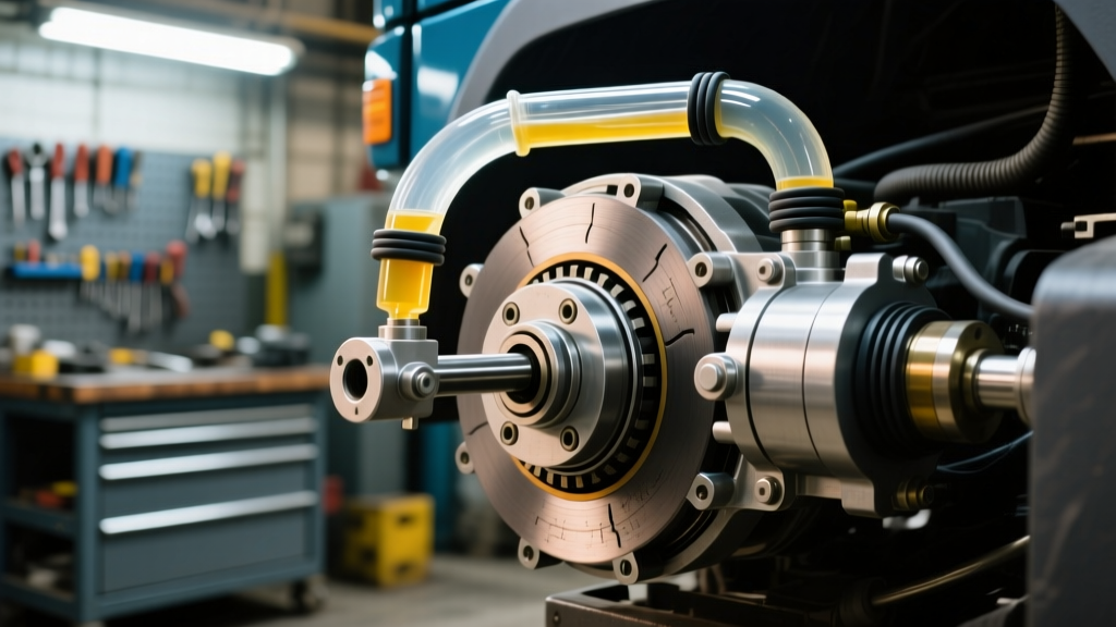
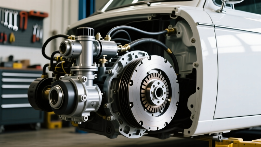
Upgrading to an SM465 hydraulic clutch conversion kit is the definitive solution. By replacing the mechanical linkage with a sealed hydraulic master and slave cylinder system, you eliminate flex, reduce pedal effort, and guarantee consistent throwout bearing travel. But if the hydraulic geometry is miscalculated or the system is improperly bled, clutch drag will persist. This step-by-step guide details how to properly install, adjust, and diagnose release problems in an SM465 hydraulic conversion.
Understanding SM465 Clutch Release Requirements
Before turning any wrenches, you must understand the specific release requirements of the SM465. According to Novak Adapt's SM465 Transmission Guide, the transmission features a massive 1-1/8-inch 10-spline input shaft and requires a specific bellhousing depth. To fully disengage a standard 12-inch diaphragm or Borg & Beck style clutch pressure plate, the throwout bearing must travel a minimum of 0.500 to 0.600 inches against the pressure plate fingers.
If your hydraulic slave cylinder cannot provide this exact volume of fluid displacement and physical travel, the clutch will drag. Furthermore, the SM465 external clutch fork requires a precise pivot ratio. If the slave pushrod acts on the wrong side of the fulcrum, you will either run out of pedal travel before achieving full release, or you will over-extend the clutch disc hub, causing catastrophic binding on the input shaft.
Step-by-Step Installation and Adjustment Guide
Step 1: Master Cylinder Sizing and Pedal Ratio
The most common cause of a soft pedal and incomplete release after a conversion is an improperly sized master cylinder. The factory GM hydraulic trucks (1985-1991) utilized a 3/4-inch bore master cylinder (commonly cross-referenced with Raybestos part number MC390538).
- Pedal Ratio Check: Measure the distance from the pedal pivot to the pushrod pin, and divide it by the distance from the pivot to the footpad. You need a minimum 5:1 ratio to generate the 600-800 PSI required to actuate the slave cylinder.
- Pushrod Adjustment: The master cylinder pushrod must have exactly 1/16-inch of free play before engaging the piston. Zero free play will block the internal compensation port, trapping fluid and causing the clutch to drag continuously.
Step 2: External Slave Cylinder and Fork Geometry
Most SM465 hydraulic clutch conversion kits utilize an external push-type slave cylinder mounted to the bellhousing. The factory GM slave cylinder (often a 7/8-inch bore) is ideal for the SM465's heavy clutch fork.
- Mounting Bracket Fabrication: Ensure the slave cylinder is perfectly parallel to the clutch fork. Angular misalignment will bind the pushrod, robbing you of up to 0.150 inches of critical travel.
- Pushrod Length and Free Play: The slave pushrod must have 1/8-inch of free play at the fork. If the pushrod is adjusted too tight, it will pre-load the throwout bearing against the spinning pressure plate fingers. This not only causes premature bearing failure but generates enough heat to warp the clutch disc, leading to severe clutch drag.
- Travel Verification: Have an assistant depress the pedal while you measure slave pushrod travel. You must see a minimum of 0.750 inches of pushrod movement to yield the required 0.550 inches of throwout bearing travel inside the bellhousing (accounting for fork ratio).
Step 3: Line Routing and Advanced Bleeding Techniques
Air is the enemy of hydraulic release. Because the SM465 slave cylinder sits lower than the master cylinder, and the hard line often routes over the frame rail, air pockets easily trap themselves in the high points of the system. As noted in Advance Adapters Technical Vault, gravity bleeding is rarely sufficient for heavy-duty truck hydraulic clutch systems.
Pro-Tip: Never use DOT 5 silicone fluid in an SM465 hydraulic conversion. It compresses more than glycol-based fluids under high heat and pressure, leading to a spongy pedal and incomplete clutch release. Stick to high-quality DOT 3 or DOT 4 fluid.
The Reverse-Bleed Method: If standard top-down bleeding fails, use a syringe and clear tubing to push DOT 4 fluid from the slave cylinder bleeder screw up into the master cylinder reservoir. This forces trapped air out of the highest point in the system. Ensure the master cylinder cap is off and the reservoir is partially empty to prevent overflow.
Troubleshooting Matrix: Clutch Drag and Release Problems
If you have completed the installation and are still experiencing clutch drag, use the following diagnostic matrix to isolate the failure point.
| Symptom | Probable Cause | Diagnostic Step | Correction Protocol |
|---|---|---|---|
| Grinding into Reverse only | Incomplete release / Air in line | Measure slave pushrod travel (Target: >0.750") | Reverse-bleed system; check master comp port |
| Creeping in 1st gear, pedal to floor | Warped clutch disc / Input shaft binding | Inspect SM465 input shaft splines for rust/burrs | Clean splines, apply minimal high-temp grease |
| Pedal feels solid but won't release | Slave pushrod adjusted too tight (Pre-load) | Check for 1/8" free play at the clutch fork | Shorten pushrod to restore free play |
| Pedal slowly sinks to the floor | Internal master cylinder bypass / Seal failure | Hold pedal down for 60 seconds; watch for drop | Replace master cylinder (Verify 3/4" bore) |
| Vibration upon release, then drag | Worn pilot bearing / Input shaft misalignment | Check pilot bearing ID for play on input shaft tip | Replace with sealed ball-bearing pilot bushing |
Advanced Diagnostics: When the Hydraulics Aren't the Issue
It is a common mistake to blame the SM465 hydraulic clutch conversion kit when the root cause lies inside the bellhousing. If your hydraulic travel is verified at a true 0.600 inches at the throwout bearing, and the system holds pressure without bleeding down, your drag issue is mechanical.
The Pilot Bearing Trap
The SM465 input shaft is incredibly heavy and long. If the pilot bearing in the back of the crankshaft is worn, seized, or incorrectly sized, it will support the input shaft at an angle. When you depress the clutch pedal, the disc cannot slide freely off the misaligned 1-1/8-inch splines. The engine's rotational energy continues to transfer through the bound disc, causing violent chatter and clutch drag. Always use a sealed ball-bearing style pilot bearing (not a porous bronze bushing) and verify it slides onto the input shaft tip with light finger pressure before mating the transmission to the engine block.
Flywheel Step Height and Machining
Clutch drag can also be caused by improper flywheel step height. The SM465 typically pairs with a 12-inch or 14-inch clutch setup. If the flywheel was resurfaced without maintaining the correct step height (the distance between the friction surface and the pressure plate mounting pad), the pressure plate cannot fully retract when the throwout bearing pushes the fingers. For standard GM 12-inch diaphragm clutches, the step height must be strictly maintained to factory tolerances (usually between 0.400" and 0.600" depending on the exact pressure plate model). A deviation of just 0.030 inches can result in a clutch that refuses to fully disengage, regardless of how perfectly your hydraulic conversion is tuned.
Final Torque Specs and Reassembly Notes
When finalizing your conversion and reinstalling components to cure drag issues, adhere strictly to these torque specifications to prevent bellhousing misalignment, which binds the clutch fork:
- Flywheel to Crankshaft (Grade 8 Bolts): 75-85 lb-ft (use red Loctite 271)
- Pressure Plate to Flywheel: 35 lb-ft in a star pattern
- Bellhousing to Engine Block: 35-45 lb-ft
- Transmission to Bellhousing: 45-50 lb-ft
- Clutch Fork Pivot Ball: 20-25 lb-ft (apply anti-seize to the ball stud, but keep grease away from the friction surfaces)
By systematically verifying hydraulic volume, ensuring precise pushrod geometry, and eliminating internal mechanical binding, your SM465 hydraulic clutch conversion will deliver a buttery-smooth pedal and crisp, drag-free shifts for hundreds of thousands of miles.