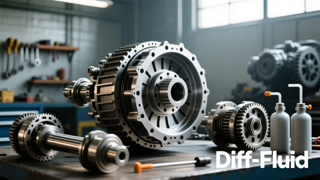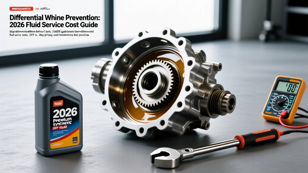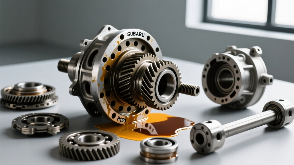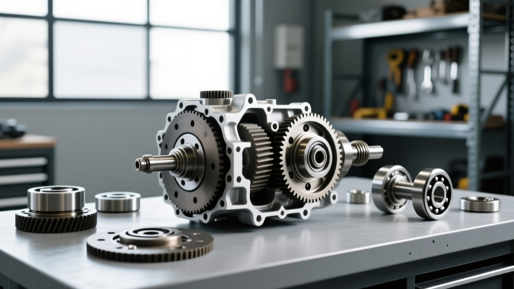
Rebuilding the differential in a premium garden tractor is fundamentally different from servicing a solid rear axle on a pickup truck. In a modern riding mower with locking differential, the differential gears, mechanical locking dog collar, and hydrostatic drive pumps all share the exact same fluid sump inside the transaxle housing. This shared-sump architecture means that a failing differential lock doesn't just result in lost traction; the resulting metal shavings circulate through the fluid and can catastrophically score the hydrostatic pump's swashplate and cylinder block.
Whether you are servicing a Hydro-Gear GT-3100 found in high-end John Deere X700 series tractors or a Tuff Torq K72 with a mechanical diff lock, a complete differential rebuild requires meticulous attention to seal integrity, dog-clutch engagement tolerances, and precise fluid specifications. As of 2026, modern synthetic fluid formulations offer vastly improved shear stability, but they cannot compensate for worn engagement pawls or degraded carrier bearings. This step-by-step guide will walk you through the complete teardown, rebuild, and fluid evacuation procedures required to restore your mower's drivetrain to factory specifications.
Diagnosing Pre-Rebuild Symptoms
Before splitting the transaxle case, verify that the differential is indeed the source of the failure. Common symptoms of a failing locking differential in a shared-sump transaxle include:
- Grinding upon engagement: Worn engagement dogs or a bent shift fork preventing the locking collar from fully seating into the side gear.
- Asymmetric wheel spin: One wheel spinning while the other remains stationary despite the diff-lock lever being fully engaged, indicating stripped pawls or a sheared roll pin.
- Hydrostatic whining: A high-pitched whine from the transaxle during tight turns, signaling that the differential side gears are binding due to degraded fluid or bearing preload loss.
Essential Tools and OEM Parts List
Do not attempt this rebuild with generic hardware store components. The internal pressures of a hydrostatic transaxle will blow out generic seals. Source OEM or high-grade aftermarket equivalents.
| Category | Item / Specification | Estimated Cost (2026) |
|---|---|---|
| OEM Seal & Gasket Kit | Hydro-Gear #19432 or Tuff Torq #79988 | $45 - $65 |
| Locking Mechanism | Diff Lock Collar, Pawl Springs, Shift Fork | $80 - $120 |
| Bearings | Carrier & Axle Tapered Roller Bearings | $50 - $90 |
| Fluid | 5W-50 Full Synthetic (4 Quarts) | $60 - $85 |
| Specialty Tools | Internal Snap Ring Pliers, 12-Ton Press, Torque Wrench | N/A |
Step 1: Chassis Extraction and Fluid Evacuation
Begin by safely elevating the rear of the riding mower using jack stands placed under the frame rails—never rely solely on a hydraulic jack. Remove the rear wheels, axle retaining clips, and the mechanical linkage connecting the dashboard diff-lock lever to the transaxle shift arm.
Locate the 3/8-inch magnetic drain plug on the bottom of the transaxle housing. Place a catch pan capable of holding at least 150 ounces. As the fluid drains, inspect it closely. If the 5W-50 fluid is milky, water has breached the axle seals. If it is glittering with fine metallic paste, the hydrostatic pump is likely scoring. If you find large, jagged metal chunks, the differential ring gear or locking dogs have suffered catastrophic failure. Clean the magnetic plug thoroughly with brake cleaner before reinstallation.
Step 2: Case Splitting and Differential Carrier Removal
Once the transaxle is on the workbench, remove the external cooling fan, reservoir tank, and hydraulic lines. Cap all hydraulic ports immediately to prevent dust ingress. Unbolt the perimeter case flange bolts (typically 10mm and 12mm). Use a soft-faced mallet to gently separate the case halves; never pry between the machined aluminum mating surfaces with a screwdriver, as this will cause permanent fluid leaks.
With the case open, lift the differential carrier assembly out of the lower housing. You will now have clear access to the ring gear, pinion, and the mechanical locking collar. According to Hydro-Gear Technical Support documentation, the locking mechanism relies on a sliding collar that engages with cast teeth on the internal side gears. Inspect these teeth for rounding or shearing.
Step 3: Inspecting and Rebuilding the Locking Dog Mechanism
The most common failure point on a riding mower with locking differential is the engagement collar. Over time, operators engage the diff lock while the wheels are spinning at different speeds, causing the dog teeth to clash and grind. This rounds off the leading edges of the teeth, resulting in the lock popping out under heavy load.
- Remove the snap ring securing the locking collar to the differential carrier.
- Extract the collar and inspect the internal shift fork groove for excessive wear.
- Replace the engagement pawls, springs, and the collar itself. Even minor rounding on the dog teeth will cause the lock to disengage when climbing steep inclines.
- Apply a thin layer of assembly lube to the new collar to ensure smooth sliding action on the carrier splines.
Step 4: Bearing, Seal, and Reassembly Procedures
Using a hydraulic press, remove the old tapered roller bearings from the differential carrier and the transaxle housing. Press the new bearings into place, ensuring they are fully seated against the machined shoulders. Critical E-E-A-T Note: Improper bearing preload will cause the ring gear to run out of alignment with the pinion, leading to rapid gear whine and tooth shear.
Before mating the case halves, install the new axle seals from your OEM kit. Coat the outer lip of the seals with a light film of fresh 5W-50 oil to prevent dry-start tearing. Apply a 2mm bead of high-temperature RTV silicone (such as Permatex Ultra-Black) to the lower case half's mating surface. Carefully lower the upper case half, aligning the shift fork into the locking collar groove. Torque the perimeter flange bolts in a criss-cross pattern to 14-18 Nm (10-13 ft-lbs). Do not overtighten, as the aluminum housings will strip easily.
Step 5: Precision Fluid Fill and Hydrostatic Bleeding
Because the differential shares its lubrication with the hydrostatic drive system, fluid selection is non-negotiable. While older manuals may have suggested 10W-30, modern 2026 service bulletins from major transaxle manufacturers strictly mandate 5W-50 Full Synthetic for heavy-duty GT-series transaxles to maintain viscosity under the extreme shear forces of the hydraulic pump.
Fill the transaxle through the top expansion port until the fluid reaches the bottom of the filler neck threads (typically 135 to 145 ounces, depending on the exact cooling line volume). Reinstall the expansion cap and reconnect the hydraulic lines.
The Bleeding Process: Air trapped in the shared sump will cause the differential to starve for lubrication during initial operation. With the rear wheels elevated and the engine running at half throttle, slowly push the hydrostatic control arms forward and backward for 5 minutes. Next, engage the locking differential and disengage it repeatedly to cycle fluid into the side gear cavities. Finally, lower the mower and drive it in wide, slow figure-8 patterns for 15 minutes to purge residual air from the system.
Troubleshooting Post-Rebuild Diff Lock Issues
If the differential lock fails to engage after the rebuild, do not force the lever. First, verify that the external shift linkage is not binding against the mower's chassis or debris shields. Second, check the fluid level; low fluid can cause aeration, resulting in a spongy hydraulic feel that masks mechanical engagement. For comprehensive parts diagrams and torque sequences specific to your exact mower model, cross-reference your serial number with the Jack's Small Engines Parts Database.
By adhering to these precise teardown procedures, utilizing OEM seal kits, and strictly following 5W-50 fluid specifications, you will ensure your riding mower's locking differential provides reliable, traction-multiplying performance for hundreds of operating hours to come.