The Role of the Auto Clutch Plate in Modern Automatics
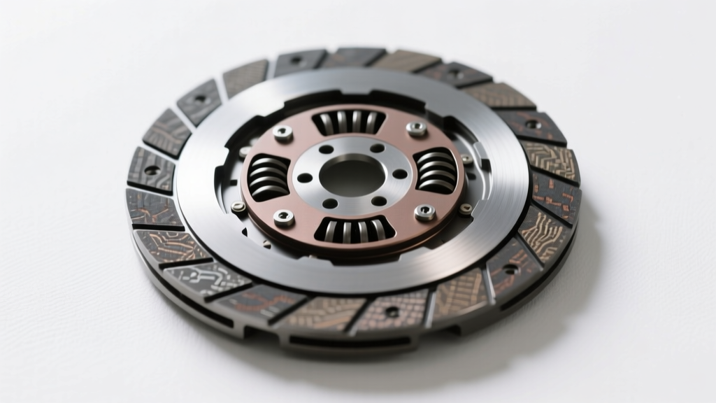
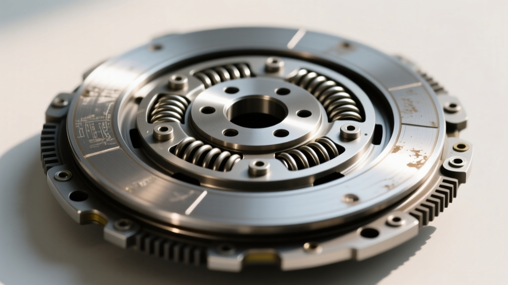
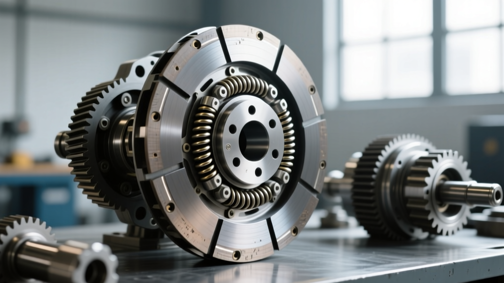
When enthusiasts discuss manual transmissions, the term 'clutch disc' dominates the conversation. However, in the realm of automatic transmissions, torque transfer is managed by a complex, multi-disc arrangement known as a clutch pack. Within these drums, the individual auto clutch plate components—alternating between friction discs and steel separator plates—are the unsung heroes of gear ratio changes. Whether you are rebuilding a legendary GM 4L60E, a heavy-duty 6L80, or a sophisticated ZF 8HP, understanding how to properly measure, stack, and set the clearance for these clutch packs is the difference between a transmission that shifts like glass and one that destroys itself in 500 miles.
This step-by-step how-to guide bypasses basic theory and dives straight into the metrology, metallurgy, and mechanical precision required to rebuild automatic transmission clutch packs in a professional shop environment.
Essential Tools and Component Budgeting
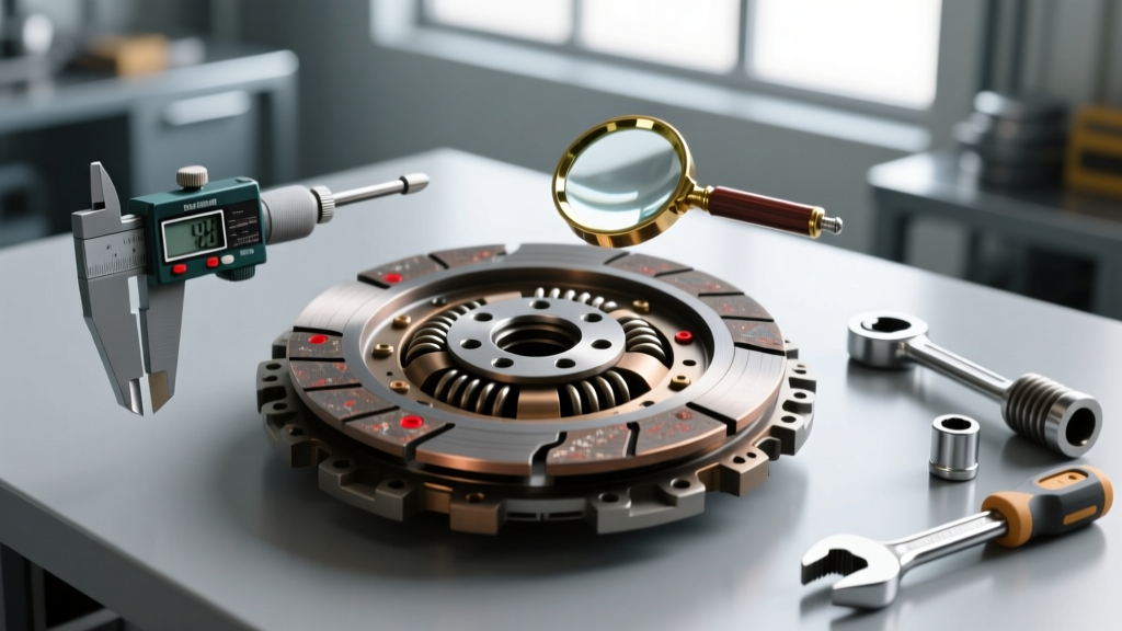
Before cracking open the transmission case, you must assemble the correct metrology tools and source high-quality replacement components. Guessing clearances with a standard feeler gauge is a recipe for delayed engagements and burnt frictions.
- Dial Indicator with Magnetic Base: Must read in 0.001-inch increments.
- Internal/External Snap Ring Pliers: Heavy-duty tips to handle thick selective snap rings.
- Feeler Gauge Set: For initial static checks and verifying wave plate heights.
- ATF for Pre-Soaking: Must match the OEM specification (e.g., Dexron VI for GM, Mercon LV for Ford).
- Component Budget: A premium Raybestos GPZ clutch pack module for a 6L80 typically ranges from $250 to $350. An Alto Red Eagle performance kit for a 4L60E 3-4 clutch pack averages $120 to $160. Always budget an extra $50 for selective thickness snap rings and shims.
Step-by-Step Rebuild and Clearance Setup
Phase 1: Disassembly and Metallurgical Triage
Begin by removing the clutch pack snap ring using your internal pliers. Carefully lift the pressure plate and extract the auto clutch plate stack. As you disassemble, lay the plates out in the exact order they were removed. Inspect the steel separator plates for 'bluing'—a distinct purple or blue discoloration indicating the steel exceeded 400°F (204°C) due to slippage. If the steels are blued, warped, or scored, they must be replaced. Reusing warped steels will cause uneven clamping pressure, leading to localized hot spots and rapid failure of the new friction plates. According to the Automatic Transmission Rebuilders Association (ATRA), microscopic warping as small as 0.003 inches can compromise the hydraulic seal of the clutch pack.
Phase 2: The Pre-Soak Protocol
Never install a dry friction plate into an automatic transmission. The porous friction material must be fully saturated with Automatic Transmission Fluid (ATF) to prevent immediate glazing upon the first apply.
Pro-Tip: Submerge the new friction plates in a clean pan of the exact ATF the transmission will use. Allow them to soak for a minimum of 30 minutes. If you are using high-performance Kevlar or Graphite-infused plates (like Raybestos GPZ), a 45-minute soak ensures the deep-pore resin matrix is fully primed.
Phase 3: Stacking and Piston Stroke Verification
Begin restacking the clutch drum. The sequence almost always dictates that a steel plate goes in first against the apply piston or cushion ring, followed by a friction plate, alternating until the stack is complete.
Pay special attention to waved apply plates or cushion rings, commonly found in the GM 6L80 4-5-6 clutch pack. These components are designed to absorb the initial hydraulic shock of the apply piston. If your aftermarket kit replaces a waved plate with a flat plate, you must adjust your total clearance to account for the loss of the wave's travel, otherwise, the shift will be brutally harsh.
Phase 4: Dial Indicator Clearance Measurement
This is the most critical step in the rebuild. Place the top pressure plate into the drum and install the thickest snap ring you have to act as a hard stop.
Mount your dial indicator on the transmission case or a magnetic stand, resting the plunger directly on the pressure plate. Zero the gauge. Using a pick or small screwdriver, gently pry the pressure plate upward until it hits the snap ring. Read the dial indicator. This measurement is your total clutch pack clearance.
The industry standard formula for total clearance is 0.010 to 0.015 inches per friction plate. For example, if your clutch pack contains 5 friction plates, your target total clearance should be between 0.050 and 0.075 inches. For high-performance or heavy-towing applications, leaning toward the tighter side (0.010 per plate) reduces piston travel time, resulting in faster, firmer shifts. For daily drivers, the looser end (0.015 per plate) promotes smoother, more forgiving engagements.
OEM vs. Performance Clearance Data Matrix
Clearance specifications vary wildly depending on the transmission architecture and the friction material composition. Below is a reference matrix for common modern automatic transmissions. For deeper technical bulletins on clutch apply pressures, refer to the Sonnax Technical Resources library.
| Transmission Model | Clutch Pack | Friction Count | OEM Target Clearance | Performance Target |
|---|---|---|---|---|
| GM 4L60E | 3-4 Clutch | 6 | 0.060' - 0.090' | 0.045' - 0.060' |
| GM 6L80 | 4-5-6 Clutch | 5 | 0.050' - 0.075' | 0.040' - 0.055' |
| ZF 8HP (70/90) | Clutch A (1-2-3) | 5 | 0.045' - 0.065' | 0.035' - 0.050' |
| Ford 6R80 | Direct Clutch | 6 | 0.060' - 0.085' | 0.050' - 0.065' |
Edge Cases: Wave Plates, ZF Mechatronics, and Glazing
When rebuilding modern units, you will encounter engineering nuances that deviate from the standard 'stack and measure' protocol. In the ZF 8HP series, the clutch drums are often integrated with the piston, and clearance is adjusted not by a traditional snap ring, but by selecting a specific thickness backing ring or selective shim provided in the Raybestos Powertrain master overhaul kits. Failing to use the selective shim will result in the piston bottoming out in its bore before the clutch pack is fully clamped, leading to catastrophic slip.
Another common edge case is 'glazing.' If a customer complains of flaring between gears, and you pull the auto clutch plate stack to find the friction material looks shiny and smooth like glass, the issue is rarely the plates themselves. Glazing is a symptom of low hydraulic line pressure, a leaking apply piston seal, or a faulty solenoid in the valve body. Replacing the plates without addressing the hydraulic leak will only result in the new plates glazing within a few hundred miles.
Final Assembly and Snap Ring Seating
Once your dial indicator confirms the clearance is within the target specification using the correct selective snap ring, remove the snap ring one last time. Apply a generous coat of assembly lube or ATF to the top pressure plate and the snap ring groove.
Reinstall the snap ring, ensuring the beveled edge faces upward (toward the top of the drum) if applicable. Use a small pick to run along the entire circumference of the snap ring groove. You must feel and hear the ring 'snap' into the groove at every point. A partially seated snap ring will blow out under high line pressure, instantly destroying the clutch pack and scattering metal debris throughout the newly rebuilt transmission.
By respecting the metrology of the auto clutch plate stack and adhering to strict clearance tolerances, you ensure the hydraulic system can modulate shifts flawlessly, extending the lifespan of the transmission far beyond OEM expectations.