The Myth of Clutch Pressure Plate Repair
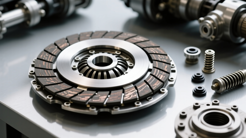
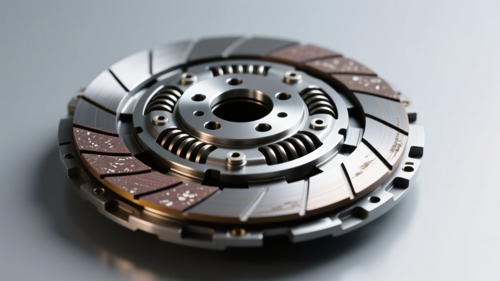
When facing drivetrain slippage or a spongy pedal, the initial instinct for many enthusiasts and budget-conscious shops is to search for a clutch pressure plate repair solution. However, in modern manual transmission applications, repairing a fatigued pressure plate is largely a myth. Unlike vintage Borg & Beck multi-finger designs—which could sometimes be rebuilt by re-tensioning levers and replacing worn pivot pins—modern diaphragm spring pressure plates rely on the precise metallurgical temper of a single conical spring. Once this steel yields from heat cycling or aggressive clutch dumping, the clamp load is permanently compromised. Heat spotting on the cast iron friction ring further warps the mating surface, causing localized loss of clamping force. Therefore, true 'repair' actually means precise diagnosis, replacement, and, most importantly, selecting the correct upgraded clamp load for your specific torque output and drivetrain limits.
The Physics of Diaphragm Springs and Clamp Load
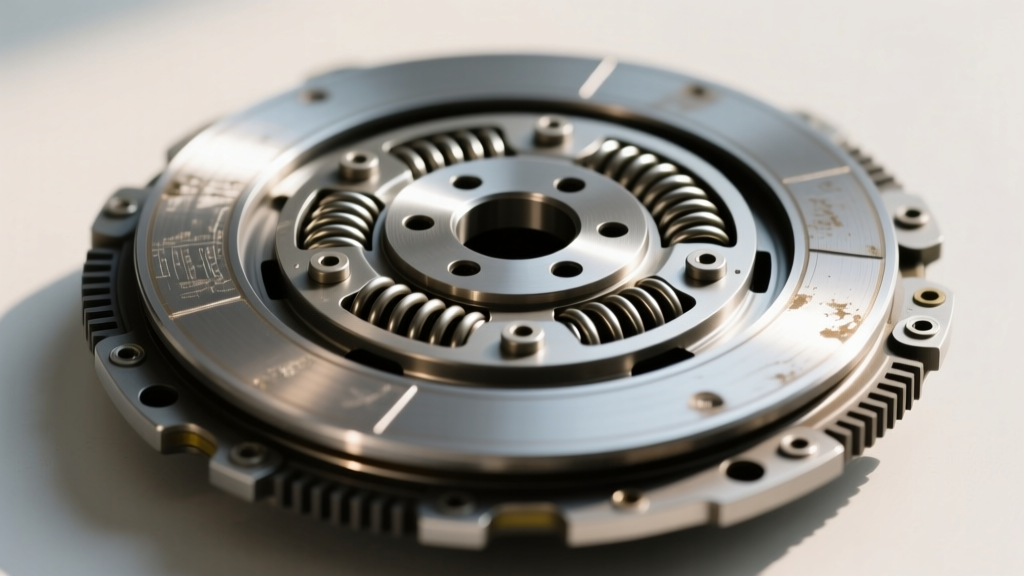
Clamp load is the axial force, measured in pounds (lbs) or Newtons (N), that the pressure plate exerts on the friction disc against the flywheel. This force is generated by the diaphragm spring acting over a fulcrum ring. The mechanical advantage (or ratio) of the spring dictates the relationship between the clamp load at the friction surface and the release load required at the throwout bearing.
A common misconception is that higher clamp load universally equals better performance. While it increases torque capacity, it also exponentially increases the load on your release bearing, hydraulic system, and engine internals. As of 2026, advanced metallurgical treatments like cryogenic processing and proprietary maraging steels allow manufacturers like ACT Clutches to achieve higher clamp loads with thinner, lighter spring profiles, reducing rotational mass without sacrificing clamping force.
The Torque Capacity Formula:
Torque Capacity (lb-ft) = (Clamp Load × Coefficient of Friction (μ) × Mean Radius (inches) × Number of Friction Surfaces) / 12
Understanding this formula is critical. If you need to hold 600 lb-ft of torque, you can either increase the clamp load (resulting in a stiffer pedal) or increase the coefficient of friction and mean radius (using a more aggressive disc material or a larger diameter flywheel).
Friction Materials and Torque Capacity Matrix
Selecting the right clamp load requires pairing it with the appropriate friction material. An organic disc requires significantly less clamp load to achieve the same torque capacity as a sintered iron disc, but it will burn up under high-slip conditions. Below is a technical matrix to guide your selection:
| Friction Material | Coefficient (μ) | Max Temp (°F) | Engagement Style | Required Clamp Load Strategy |
|---|---|---|---|---|
| Organic / Kevlar Blend | 0.25 - 0.28 | 450 | Smooth, progressive | High clamp load needed for high torque |
| Full Kevlar / Aramid | 0.30 - 0.33 | 600 | Slightly aggressive | Moderate clamp load; requires flywheel heat dissipation |
| Cerametallic (Puck) | 0.35 - 0.38 | 850 | Abrupt, high grab | Lower clamp load can hold high torque; harsh on drivetrain |
| Sintered Iron | 0.40 - 0.45 | 1000+ | On/Off, race only | Very high clamp load required; used in multi-disc drag setups |
Drivetrain Limits: The Hidden Cost of Excessive Clamp Load
When upgrading from a stock 1,800 lb clamp load to a heavy-duty 3,200 lb unit, the collateral stress on surrounding components is often ignored until catastrophic failure occurs.
Crankshaft Thrust Bearing Limits
The throwout bearing pushes against the diaphragm spring fingers, which in turn pushes the entire pressure plate assembly forward against the flywheel. This axial load is transferred directly through the flywheel bolts into the crankshaft flange and absorbed by the crankshaft thrust bearing. Most production V8 engines (like the GM LS or Ford Coyote) feature thrust bearings designed to handle continuous axial loads of roughly 300 to 400 lbs. If your pressure plate requires 600 lbs of release load to disengage, and you ride the clutch in stop-and-go traffic, you will rapidly accelerate thrust bearing wear, leading to crank walk and total engine destruction.
Hydraulic Master Cylinder Sizing
High clamp load demands more hydraulic volume and pressure. A stock 0.75-inch bore master cylinder will result in an unbearably stiff pedal when paired with a 3,000+ lb pressure plate. Upgrading to a 0.875-inch or 1.0-inch bore master cylinder (such as the Tilton 7/8-inch adjustable unit) reduces pedal effort by increasing hydraulic pressure, though it requires slightly more pedal travel to achieve full disengagement.
Flywheel Step Height: The Silent Clamp Load Killer
One of the most frequent causes of premature clutch failure and perceived 'low clamp load' is incorrect flywheel step height. The step is the difference in elevation between the flywheel friction surface and the pressure plate mounting surface. According to technical documentation from RAM Clutches, if the machine shop resurfaces the flywheel friction ring but ignores the mounting pads, the step height is altered.
- Positive Step (e.g., GM LS 2-piece RMS): The friction surface sits higher than the mounting pads (typically 0.015 to 0.025 inches). If machined flat (0.000), the diaphragm spring is pre-loaded too far, drastically reducing its dynamic clamping range and causing slip under load.
- Negative Step (e.g., Ford Modular V8): The friction surface sits lower than the mounting pads. Incorrect step here causes the throwout bearing to over-extend, leading to bearing explosion and incomplete disengagement.
Always measure step height with a dial indicator and straight edge before installation. If the step is out of spec, use precision steel shims (like RAM part # 4005) between the pressure plate and flywheel to restore the exact factory geometry and intended clamp load.
Real-World Case Study: LS3 Tremec T56 Magnum Build
Consider a 2026 restomod build featuring a 525 lb-ft naturally aspirated LS3 mated to a Tremec T56 Magnum (26-spline input). The builder initially installed a generic 3,500 lb single-disc 'race' pressure plate. The result was a 75 lb pedal effort that caused severe firewall flex and rapid throwout bearing wear.
The Solution: We transitioned to a dual-disc setup with a lower static clamp load but doubled friction surfaces. By utilizing the McLeod Street Twin (Part # 75207 for GM 26-spline), which utilizes two organic/ceramic blended discs, the system achieves a torque capacity of over 1,200 lb-ft with a diaphragm spring rated at only 2,400 lbs of clamp load. This maintained a street-friendly 35 lb pedal effort while providing zero-slip performance.
Critical Installation Torque Specifications
Proper torque sequence and specs are vital to prevent pressure plate distortion, which artificially alters clamp load distribution across the disc:
- Pressure Plate to Flywheel (M8 x 1.25 bolts): 25-30 lb-ft (34-40 Nm) in a star pattern.
- Pressure Plate to Flywheel (M10 x 1.5 bolts): 45-55 lb-ft (61-75 Nm) in a star pattern.
- Flywheel to Crankshaft (ARP Bolts with Moly Lube): 80-90 lb-ft (108-122 Nm) in a crisscross pattern.
- Clutch Fork Pivot Ball: 25 lb-ft with medium threadlocker.
Ultimately, clutch pressure plate repair is less about fixing a broken part and more about engineering the correct clamp load, friction coefficient, and hydraulic geometry for your specific chassis. By respecting the physics of diaphragm springs and the axial limits of your engine block, you can build a manual drivetrain that is both bulletproof and street-drivable.