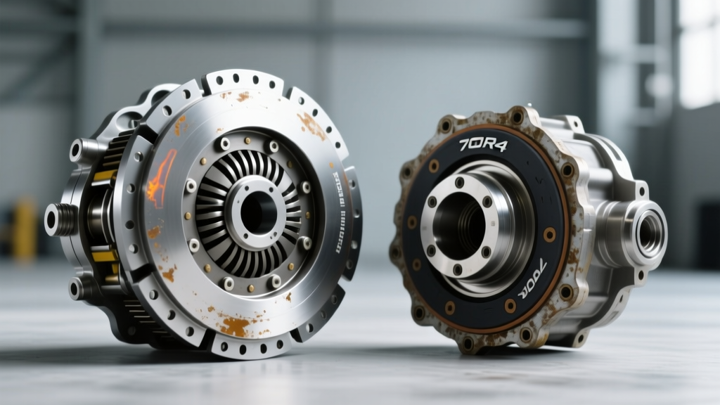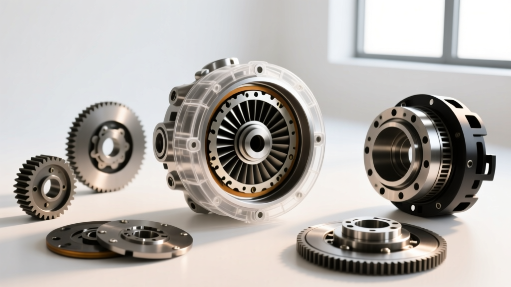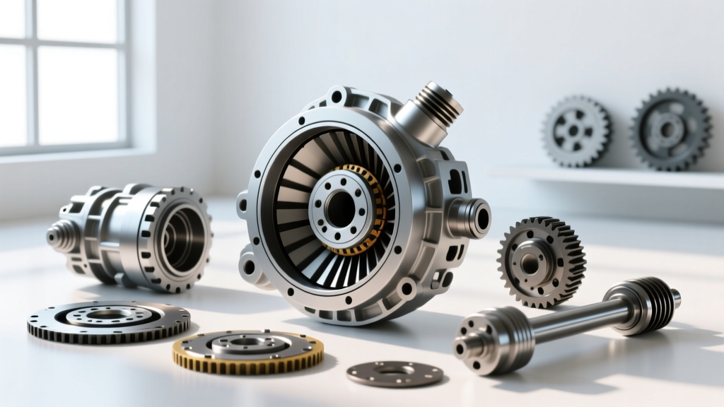
Torque converter clutch (TCC) shudder is one of the most misunderstood and frequently misdiagnosed drivability complaints in modern automatic transmissions. Often described by drivers as a 'rumble strip' sensation or a rhythmic vibration during light-throttle highway cruising, shudder occurs when the TCC fails to maintain a steady micro-slip during the slip-regulate phase. As we navigate the 2026 automotive landscape, where transmissions like the GM 6L80, Ford 10R80, and ZF 8HP rely on aggressive pulse-width modulation (PWM) for fuel economy, the frictional demands on transmission fluid and clutch materials are higher than ever.
While many technicians immediately condemn the torque converter, a rigorous preventive maintenance approach can often resolve the issue without dropping the transmission. However, when chemical and hydraulic preventive measures fail, understanding exactly how to remove torque converter assemblies becomes mandatory to inspect the internal clutch lining, hub, and damper springs. This guide bridges the gap between preventive fluid diagnostics and mechanical extraction.
Decoding the Slip-Regulate Phase
To diagnose shudder, you must understand the hydraulics of the slip-regulate phase. Modern transmissions rarely apply the TCC at a simple 100% lockup. Instead, the transmission control module (TCM) commands a controlled slip—typically between 20 and 40 RPM—to dampen engine torsional vibrations. This is achieved by rapidly pulsing the TCC PWM solenoid. If the friction coefficient of the fluid degrades, or if the clutch lining becomes glazed, the micro-slip oscillates wildly. The result is a low-frequency vibration (usually between 25Hz and 45Hz) that transfers directly through the driveline.
Diagnostic Matrix: Shudder vs. Misfire vs. Driveline Vibration
Before attempting any preventive flush or mechanical removal, verify the source of the vibration using a scan tool to monitor TCC slip RPM and a chassis ear or NVH (Noise, Vibration, and Harshness) analyzer.
| Symptom Profile | TCC Shudder | Engine Misfire | Driveline/U-Joint Vibration |
|---|---|---|---|
| Trigger Condition | Light throttle, 45-65 MPH, TCC applied | Under load, various speeds, often idle | Speed-sensitive (e.g., exactly at 70 MPH) |
| Scan Tool Data | TCC Slip RPM oscillates +/- 50 RPM | Engine RPM fluctuates, misfire counters rise | TCC Slip is steady at 0 RPM or target |
| Brake Tap Test | Shudder instantly stops (TCC releases) | Vibration persists or worsens | Vibration persists until speed drops |
| Frequency (Hz) | 25 - 45 Hz | Engine order specific (e.g., 20-30 Hz) | Driveshaft rotational frequency |
Preventive Maintenance Protocols (Pre-Removal)
According to data published by the Automatic Transmission Rebuilders Association (ATRA), up to 40% of TCC shudder complaints on high-mileage GM 6L80 and 6L90 units can be resolved without mechanical teardown, provided the clutch lining has not physically disintegrated.
1. Fluid Friction Modification
Standard Dexron VI or ATF+4 fluids rely on complex friction modifier packages that deplete over time due to thermal shearing. When the fluid loses its ability to maintain a consistent coefficient of friction, shudder begins. A preventive machine flush using a dedicated friction modifier (such as Lubegard Shudder Fixx or Dr. Tranny Shudder Fix) can restore the chemical grip on the clutch disc. Note: Never use friction modifiers on ZF 8HP units filled with LifeguardFluid 8 without verifying compatibility, as ZF friction materials are highly sensitive to additive over-treatment.
2. Solenoid Screen and Valve Body Hydraulics
On the Ford 6R80 and GM 8L90, debris from degrading clutch materials often clogs the micro-screens on the TCC PWM solenoid or causes the TCC regulator valve to stick in the valve body. A preventive drop-pan service to clean the solenoid screens and install a Sonnax TCC regulator valve kit can restore proper hydraulic pressure to the converter, eliminating shudder caused by pressure starvation.
When Prevention Fails: How to Remove Torque Converter Assemblies
If fluid chemistry and hydraulic pressure tests confirm that the torque converter clutch lining is glazed, warped, or the internal damper springs are fatigued, replacement is required. Extracting the unit requires precision to avoid catastrophic damage to the transmission oil pump.
Step 1: Preparation and Draining
Disconnect the battery and raise the vehicle on a two-post lift. Remove the transmission fluid pan and filter to drain as much fluid as possible. This prevents a massive spill when the converter is unseated from the pump gear. For units like the ZF 8HP, remove the mechatronic unit to allow the valve body to drain completely, reducing the weight of the transmission during the drop.
Step 2: Flexplate and Bellhousing Separation
Remove the inspection cover to access the torque converter-to-flexplate bolts. Critical E-E-A-T Note: Never use an impact gun to remove these bolts, as the shock load can crack the flexplate or damage the converter hub. Use a flywheel holding tool and a breaker bar. On GM 6L80 applications, the M10x1.25 flexplate bolts require 35 lb-ft (47 Nm) upon reinstallation. Mark the converter to the flexplate with a paint pen to maintain factory balance.
Step 3: Supporting and Lowering the Transmission
Support the transmission oil pan with a specialized transmission jack equipped with a tilt mechanism. Remove the crossmember, driveshaft, and shift linkages. Unbolt the bellhousing from the engine block (typically 37 lb-ft / 50 Nm on most domestic V8 applications). Carefully slide the transmission rearward. Warning: If you feel resistance, stop immediately. Forcing the transmission back will snap the oil pump drive gear or crack the pump housing.
Post-Removal Inspection & The 'Three Clunks' Rule
Once the transmission is on the bench and the torque converter is removed, the true forensic diagnosis begins. Inspect the converter hub where it rides on the transmission front pump bushing. According to Sonnax Tech Resources, if the hub exhibits scoring deeper than 0.020 inches, the bushing and likely the pump housing must be replaced to prevent immediate failure of the new unit.
Furthermore, inspect the stator support shaft splines. Wear here indicates that the converter was not fully seated during a previous installation, causing the turbine to ride improperly and generating harmonic vibrations that mimic TCC shudder.
Reinstallation and Priming Protocol
Installing a new torque converter is where most catastrophic pump failures occur. You must achieve the 'Three Clunks' during installation:
- First Clunk: The converter hub engages the oil pump drive gear.
- Second Clunk: The turbine splines engage the transmission input shaft.
- Third Clunk: The stator assembly seats over the stator support shaft and one-way clutch.
Measure the seating depth. The front face of the torque converter must sit at least 1/2 inch (12mm) inside the bellhousing mating surface. If it is flush or protruding, it is not seated, and bolting the transmission to the engine will instantly destroy the oil pump.
Finally, before starting the engine, pre-fill the new torque converter with 1.5 to 2.0 quarts of the specified OEM ATF. Modern TCMs will command line pressure immediately upon startup; running the pump dry for even 10 seconds can score the pump gears and ruin the hydraulic integrity required for smooth TCC apply.
Cost Breakdown and Sourcing (2026 Estimates)
Understanding the financial scope of this repair is vital for both shop owners and consumers. Preventive maintenance is a fraction of the cost of mechanical replacement.
- Preventive Fluid Flush & Modifier: $250 - $400
- Solenoid Screen / Valve Body Service: $600 - $950 (Includes pan, filter, and fluid)
- OEM Torque Converter (e.g., GM 6L80): $450 - $750
- Remanufactured Torque Converter: $300 - $500 (Ensure it features a billet cover and upgraded clutch lining)
- Labor (R&R Transmission): 8.0 - 12.0 hours @ $150/hr ($1,200 - $1,800)
For deep-dive hydraulic schematics and valve body wear points, technicians should regularly consult Transmission Digest for model-specific service bulletins and updated PWM solenoid calibration files.
Conclusion
Torque converter shudder is a symptom of a compromised friction interface, whether caused by degraded fluid chemistry, restricted hydraulic circuits, or physical clutch failure. By employing a strict diagnostic matrix and prioritizing preventive maintenance, technicians can save customers thousands of dollars in unnecessary removals. However, when the internal friction materials are physically compromised, mastering the safe extraction, inspection, and precise reinstallation of the torque converter is the only path to restoring factory-smooth drivability.