The Evolution of Sachs in Automatic Transmissions
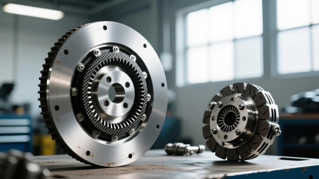
When most automotive technicians hear the phrase 'sachs clutch kits', they immediately picture manual transmission RepSets, heavy-duty pressure plates, and dual-mass flywheels. However, as of 2026, the landscape of drivetrain manufacturing has deeply integrated Sachs into the automatic transmission sector under the ZF Group umbrella. Sachs-engineered friction materials and clutch pack modules are the OEM standard inside some of the most prolific automatic transmissions on the road today, most notably the ZF 8HP series (8HP45, 8HP70, and 8HP90) found in BMW, Audi, Dodge, and Ford vehicles.
Rebuilding an automatic transmission requires a fundamentally different approach than swapping a manual clutch disc. Instead of a single friction interface, you are dealing with multiple multi-plate clutch packs (typically labeled A through E) housed within a complex drum and piston assembly. This step-by-step guide details the precise methodology for tearing down, inspecting, and rebuilding ZF 8HP automatic clutch packs using OEM-grade Sachs/ZF friction modules and master rebuild kits.
Tools and Materials Required
Before beginning the teardown, ensure your workstation is equipped with the following specialized tools and fluids. Using generic substitutes will compromise the hydraulic integrity of the mechatronic unit and clutch drums.
- OEM Friction/Steel Kit: ZF/Sachs 8HP Master Rebuild Kit (Includes frictions, steels, and piston seals)
- Transmission Fluid: ZF LifeguardFluid 8 (Part # S671 090 255) - Do not use generic Dexron VI
- Seal Installation Tools: Sonnax lip seal protectors and expansion tools (e.g., Sonnax 15700-01K)
- Measurement Tools: Digital calipers, dial indicator with magnetic base, and metric feeler gauges (0.10mm to 1.50mm)
- Assembly Lubricant: ZF LifeguardFluid 8 or dedicated assembly petrolatum for O-rings
- Torque Wrench: Inch-pound capable torque wrench for mechatronic and valve body fasteners
Step 1: Teardown and Component Inspection
The first phase of any automatic transmission rebuild is the methodical disassembly of the clutch drums. In the ZF 8HP, the clutch packs are actuated by hydraulic pressure routed directly through the mechatronic unit and the center support.
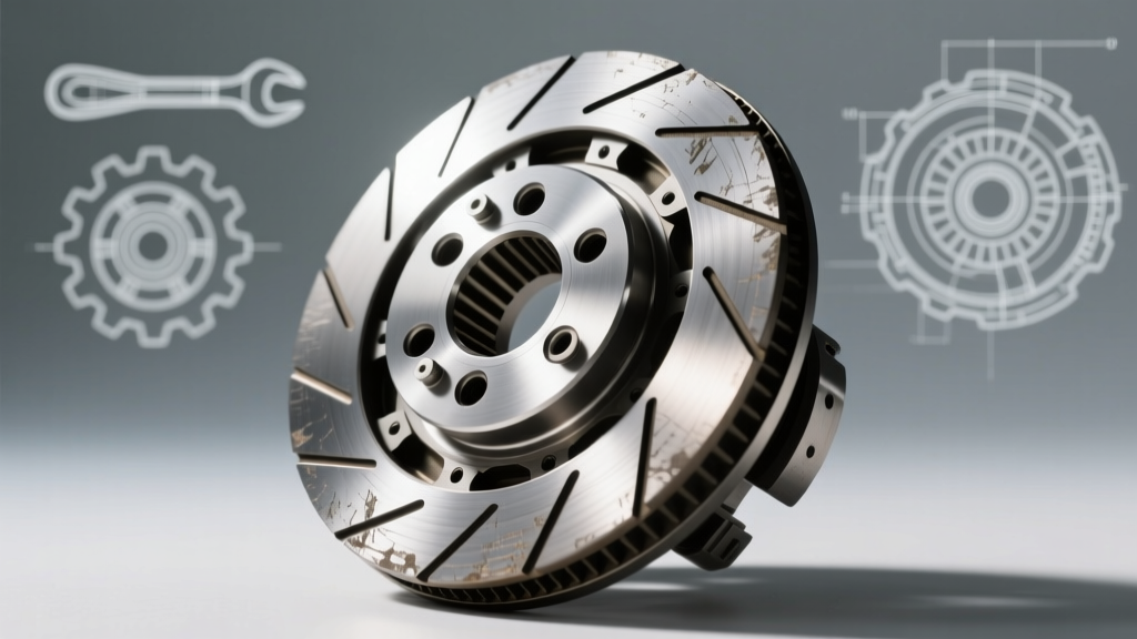
Begin by removing the selective snap rings securing each clutch pack. Carefully extract the pressure plate, followed by the alternating friction and steel separator plates. Critical Inspection Point: Examine the steel separator plates for 'bluing' or heat spotting. If the steel plates have turned a dark blue or purple, they have exceeded 400°F (204°C) due to slip-stick friction events. Blued steels lose their surface hardness and will rapidly destroy new friction plates. They must be discarded.
Next, inspect the aluminum clutch drum splines. The 8HP transmission is known for developing wear on the inner drum splines where the steel plates seat. If you feel a 'hook' or burr with your fingernail on the spline edges, the drum must be replaced or machined, otherwise, the new clutch pack will hang up, causing delayed shifts and burnt frictions.
Step 2: Friction Plate Preparation and Soaking
A common mistake among novice builders is installing dry automatic friction plates. The friction material used in Sachs/ZF clutch packs is highly porous, typically composed of a cellulose or synthetic aramid paper matrix designed to absorb and retain transmission fluid.
If installed dry, the initial hydraulic application will cause the friction material to glaze or burn before the fluid can fully permeate the matrix. Submerge all new friction plates in a clean basin of ZF LifeguardFluid 8 for a minimum of 30 minutes prior to assembly. This ensures the material is fully saturated, providing immediate lubrication and heat transfer upon the first clutch apply event.
Step 3: Piston Seal and Spring Installation
The apply pistons inside the 8HP clutch drums utilize delicate lip seals and O-rings. A microscopic nick in a piston lip seal will result in a cross-leak, bleeding off hydraulic pressure and causing a 'flare' (slip) during gear changes.
- Lubricate the new piston O-rings and lip seals generously with ZF LifeguardFluid 8.
- Use a dedicated seal ring expander tool to gently guide the piston into the drum bore. Never use metal picks or screwdrivers, as scoring the aluminum bore will ruin the drum.
- Seat the piston by applying compressed air (regulated to 40 PSI) into the drum's apply port. You should hear a distinct, solid 'thud' as the piston bottoms out against the return spring assembly.
- Verify the check-ball in the piston's release circuit moves freely. This ball allows fluid to bypass during clutch release, preventing drag.
Step 4: Stacking the Clutch Pack
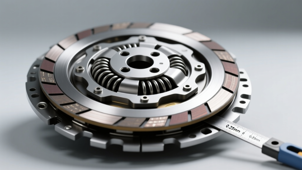
With the piston and return springs seated, begin stacking the clutch pack. The ZF 8HP utilizes a specific number of frictions and steels depending on the clutch position. Always start with a steel plate against the piston, followed by a friction, alternating until the pack is complete, and ending with a steel plate before the top pressure plate.
Handle the friction plates by their edges to avoid transferring skin oils to the friction surface. Ensure the internal splines of the friction plates align perfectly with the drum hub without forcing them, which could chip the friction material.
Step 5: Measuring and Adjusting Clutch Clearance
This is the most critical step in the rebuild process. Clutch pack clearance dictates the shift timing, shift feel, and longevity of the transmission. If the clearance is too tight, the clutch will drag, causing overheating and premature wear. If the clearance is too wide, the hydraulic piston will run out of travel before fully clamping the pack, resulting in severe slip and burnt clutches.
Install the top pressure plate and the thickest available selective snap ring. Mount a dial indicator on the transmission case, zero it against the pressure plate, and push down on the plate to measure the total travel. Compare your measurement to the OEM specifications below.
| Clutch Pack | Function / Gears | Frictions / Steels | Target Clearance (mm) | Max Allowable Wear (mm) |
|---|---|---|---|---|
| Clutch A | 1-5-6-7-8 | 4 / 4 | 0.80 - 1.10 | 1.50 |
| Clutch B | 2-6 | 3 / 3 | 0.70 - 1.00 | 1.30 |
| Clutch C | 3-5-7 | 4 / 4 | 0.90 - 1.20 | 1.60 |
| Clutch D | 4-5-6 | 3 / 3 | 0.60 - 0.90 | 1.20 |
| Clutch E | R-1-2-3-4 | 5 / 5 | 1.10 - 1.40 | 1.80 |
Note: Clearance is adjusted by selecting a different thickness pressure plate or selective snap ring from your Sachs/ZF master kit. A general rule of thumb for ZF automatics is 0.20mm to 0.25mm of clearance per friction plate.
Common Failure Modes and Edge Cases
Even with premium Sachs clutch kits, builder error or overlooked ancillary components can lead to catastrophic failure. Be vigilant regarding the following ZF 8HP-specific issues:
- Mechatronic Sleeve Adapter Leaks: The electrical connector sleeve that passes through the transmission case is notorious for leaking fluid externally and internally. Always replace this sleeve (Sonnax 15700-03K or OEM ZF equivalent) during a clutch pack rebuild.
- Center Support Cracking: The aluminum center support routes fluid to Clutches A, B, and C. Inspect the support for hairline cracks near the sealing rings. A cracked support will cause a 'neutral' condition when shifting into Reverse or Drive.
- Torque Converter Contamination: If the original transmission suffered a burnt clutch pack, the torque converter is full of friction material debris. The 8HP lock-up clutch cannot be reliably flushed. Always replace the torque converter when rebuilding burnt 8HP clutch packs to prevent debris from migrating into the mechatronic solenoids.
Final Assembly and Torque Specifications
Once all clutch packs are verified for clearance and snap rings are fully seated in their grooves, the transmission can be reassembled. When installing the mechatronic unit back into the case, ensure the manual valve linkage engages properly with the park rod.
The mechatronic-to-case fasteners (typically M6x25 bolts) must be torqued precisely to 10 Nm (7.4 lb-ft) in the sequence specified by ZF Aftermarket documentation. Over-torquing these bolts will distort the aluminum valve body casting, causing spool valves to bind and resulting in harsh, erratic shifts.
Conclusion
Rebuilding automatic clutch packs requires a meticulous adherence to clearance specifications, hydraulic cleanliness, and OEM procedures. While the aftermarket often associates the term 'Sachs clutch kits' with manual applications, leveraging OEM ZF/Sachs friction modules for automatic transmissions ensures the exact friction coefficient and shift timing engineered by the manufacturer. For further technical data on valve body wear and hydraulic circuit upgrades, consult resources from the Sonnax Transmission Company and industry publications like Transmission Digest. By following this step-by-step protocol, you can restore the ZF 8HP to its factory-standard shift quality and durability.