Decoding the Radiator Transmission Oil Cooler Diagram to Stop Overheating
Transmission overheating remains the primary catalyst for catastrophic automatic gearbox failure. Whether you are maintaining a workhorse GM 6L80, a precision-engineered ZF 8HP, or a high-capacity Ford 10R80, thermal management is non-negotiable. When automatic transmission fluid (ATF) exceeds 250°F, the fluid's shear stability collapses, clutch facings glaze, and valve body bores warp. To systematically diagnose and prevent these thermal runaway events, you must understand the hydraulic routing of your vehicle. This step-by-step guide will teach you how to leverage a radiator transmission oil cooler diagram to identify bottlenecks, verify flow rates, and implement targeted cooling upgrades.
Understanding the OEM Cooling Circuit Architecture
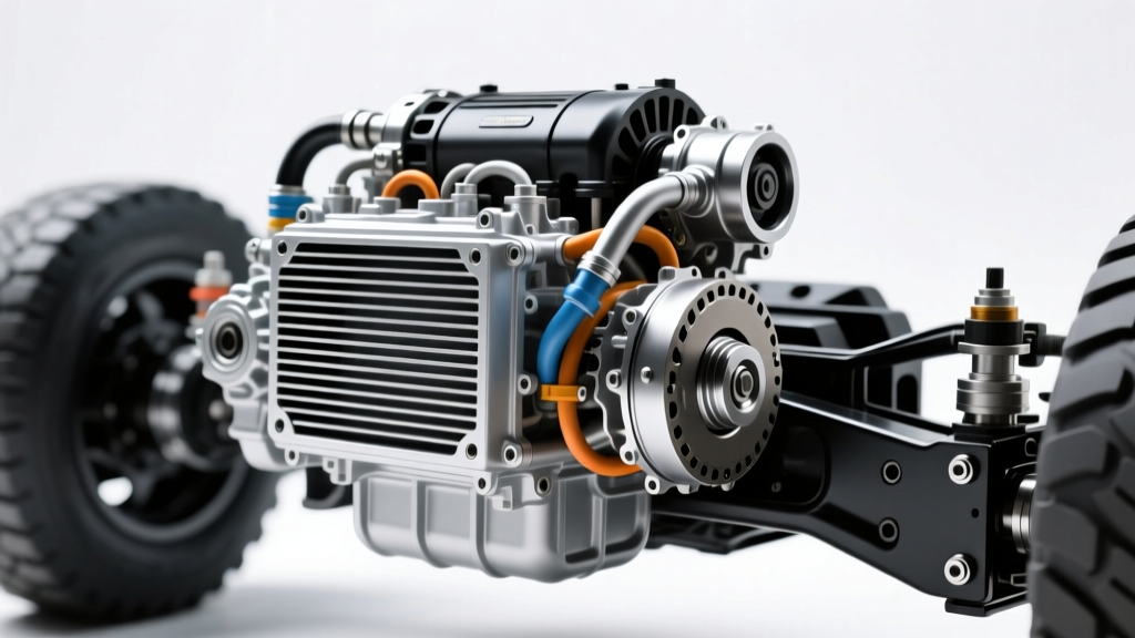
Before turning a single wrench, you must map the fluid's journey. A standard radiator transmission oil cooler diagram illustrates a closed-loop heat exchange system. Hot ATF exits the transmission case via the supply line, travels to the heat exchanger (either an internal tube-and-fin cooler submerged in the engine radiator's coolant tank, or a standalone plate-and-fin unit), sheds its thermal load, and returns to the transmission's lube and torque converter circuits.
However, modern architectures are more complex. For instance, the ZF 8HP series utilizes an Integrated Thermal Management (ITM) module featuring a wax-element thermostat. This valve restricts cooler flow during cold starts to accelerate warm-up, then opens fully once the fluid reaches approximately 185°F. If you are diagnosing an overheating ZF transmission, bypassing or misrouting the ITM based on an outdated diagram will trigger limp mode and thermal degradation.
Step 1: Verify Fluid Shear Stability and Base Level
Overheating often mimics low fluid symptoms, and vice versa. Begin by checking the ATF condition. Fluid that smells burnt or exhibits a dark, opaque brown color has exceeded its thermal limits. The friction modifiers in fluids like Dexron VI, Mercon LV, or ZF Lifeguard 8 have sheared down.
- GM 6L80/6L90: Requires Dexron VI. Total dry fill is roughly 11.2 quarts; a pan drop and filter change (ACDelco 24236933) typically requires 6.0 to 6.5 quarts.
- Ford 10R80: Requires Mercon ULV. The pan is integrated with the filter, meaning a service requires replacing the entire stamped steel or composite pan assembly (Ford JK4Z-7A106-B).
- ZF 8HP (Chrysler/BMW/Audi): Requires ZF Lifeguard 8. The plastic pan incorporates the mechatronic sleeve and filter, torqued to 10 Nm (88 lb-in) in a specific star pattern.
Step 2: Trace the Supply and Return Lines Using the Diagram
Misidentifying the supply and return lines is the most common error when installing auxiliary coolers or performing flushes. Consulting an OEM-specific radiator transmission oil cooler diagram is critical because routing varies by manufacturer. On many GM trucks, the lower radiator fitting is the supply (hot fluid from the trans), and the upper is the return. On certain Ford applications, this is reversed.
Pro-Tip: Never rely on guesswork. If you lack the factory service manual diagram, perform the 'cold-start test'. Disconnect both lines at the radiator, cap the radiator nipples, and place the disconnected lines into separate catch pans. Start the engine and idle for exactly three seconds. The line that pumps fluid into the pan is your supply line. The torque converter feeds the cooler circuit directly via the stator support shaft.
Step 3: Perform a Volumetric Flow Test
Internal radiator coolers are prone to clogging from degraded clutch material and shattered torque converter brazing. To test the internal cooler's flow capacity without removing the radiator, perform a volumetric test.
- Disconnect the return line at the transmission.
- Attach a 3/8-inch or 1/2-inch ID hose to the disconnected return line and route it into a graduated 1-quart measuring container.
- Have an assistant start the engine and let it idle in Park.
- Measure the time it takes to pump exactly one quart of fluid.
The Benchmark: A healthy GM 4L60E or 6L80 transmission pump should deliver one quart in approximately 15 to 20 seconds at idle. If it takes longer than 30 seconds, your internal radiator cooler is restricted, or the transmission's internal pump is starving. According to data published by Sonnax Technical Resources, restricted cooler flow directly correlates to delayed shift engagement and accelerated clutch pack wear due to inadequate lube circuit pressure.
Thermal Thresholds: When to Intervene
Understanding the thermal limits of your specific transmission is vital for determining whether an auxiliary cooler upgrade is necessary. The table below outlines normal operating ranges and critical failure thresholds for modern automatic transmissions.
| Transmission Model | Normal Operating Temp | Accelerated Wear Threshold | Critical Failure / Limp Mode |
|---|---|---|---|
| GM 6L80 / 6L90 | 180°F - 205°F | 230°F (Fluid degradation begins) | 265°F (TCM triggers limp mode) |
| Ford 10R80 | 190°F - 215°F | 240°F (Seal hardening risk) | 255°F (PCM limits torque output) |
| ZF 8HP (Gen 2/3) | 175°F - 195°F | 220°F (Mechatronic sleeve risk) | 260°F (Valve body thermal warp) |
Step 4: Evaluate Torque Converter Clutch (TCC) Slip
If your cooler flow is optimal and fluid levels are correct, the heat source may be internal. The Torque Converter Clutch (TCC) is designed to lock the engine to the transmission input shaft, eliminating hydraulic slippage. When the TCC solenoid or apply valve fails, the clutch slips continuously. This slippage acts like a friction brake, generating massive amounts of heat directly inside the torque converter, which is then transferred to the ATF and sent to the cooler. If your scan tool shows TCC slip RPMs greater than 20-30 RPMs at steady highway cruising, no external cooler will save the transmission. The converter must be replaced or rebuilt.
Upgrading the Cooling Circuit for Towing and Heavy-Duty Use
For vehicles subjected to towing, off-roading, or high-stall torque converters, the factory radiator cooler is insufficient. Upgrading requires integrating a high-efficiency auxiliary cooler into the circuit dictated by your radiator transmission oil cooler diagram.
Selecting the Right Auxiliary Cooler
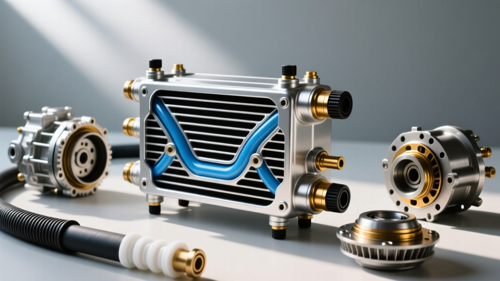
Tube-and-fin coolers are obsolete for heavy-duty applications. You must use a stacked-plate or plate-and-fin design, which offers up to 30% more surface area and superior turbulent flow characteristics.
- Hayden Rapid-Cool (Part #678): A 3/4-inch thick stacked-plate cooler rated for up to 30,000 GVW. Retail price ranges from $65 to $85.
- Derale Series 9000 (Part #13960): Features turbulator plates that agitate the fluid, preventing boundary layer stagnation. Ideal for tight engine bays, priced around $75 to $95.
The Correct Routing Sequence
The golden rule of auxiliary cooler installation is to route the fluid after the radiator, not before. The correct sequence is:
- Transmission Supply Out -> Radiator Internal Cooler In
- Radiator Internal Cooler Out -> Auxiliary Stacked-Plate Cooler In
- Auxiliary Cooler Out -> Transmission Return In
Expert Warning: Never bypass the factory radiator cooler entirely unless you are running a dedicated thermostat-controlled bypass valve for extreme cold-weather climates. The engine radiator acts as a thermal buffer, warming the ATF on cold mornings and providing a baseline temperature drop. Bypassing it completely leads to sluggish shift times and accelerated wear during cold starts, as noted in numerous field reports by the Automatic Transmission Rebuilders Association (ATRA).
Final Torque Specs and Leak Testing
When reinstalling cooler lines, always use new O-rings or crush washers. For GM quick-disconnect fittings, ensure the retaining clips snap audibly into place, and perform a secondary pull-test. If your vehicle uses threaded inverted flare or AN-style fittings on aftermarket coolers, adhere to strict torque specifications to prevent cracking the cooler end-tanks.
- Standard 3/8-inch Inverted Flare Cooler Nuts: 15 - 18 lb-ft.
- AN-6 Fittings on Aftermarket Cooler End-Tanks: 10 - 12 lb-ft (use a crowfoot wrench and avoid over-torquing the aluminum threads).
- Quick-Disconnect Retaining Clips: No torque spec; verify visual seating and physical pull resistance.
After reassembly, fill the transmission to the correct level, start the engine, cycle the shifter through all gears to prime the torque converter and cooler lines, and recheck the level at operating temperature. Inspect all connections with a UV light or clean shop towel. By mastering the radiator transmission oil cooler diagram and following this systematic diagnostic protocol, you will effectively eliminate thermal-related transmission failures and extend the service life of your drivetrain well past the 200,000-mile mark.
For further reading on hydraulic circuit diagnostics and valve body wear patterns, consult the technical archives at Transmission Digest.