The Architecture of the 6.7L Powerstroke Cooling Stack
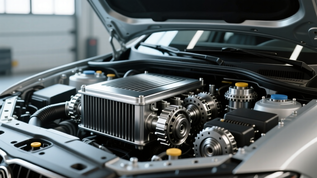
When towing heavy fifth-wheel trailers or pushing high-horsepower tunes, managing drivetrain heat is the single most critical factor in preserving your Super Duty. For Ford diesel owners, understanding the exact 6.7 powerstroke transmission cooler location is the first step toward diagnosing thermal bottlenecks and planning heavy-duty upgrades. Unlike older diesel platforms that relied solely on front-mounted air-to-fluid radiators, the modern 6.7L Powerstroke utilizes a complex, multi-stage cooling architecture designed to bring the 6R140 and 10R140 transmissions up to operating temperature quickly, while shedding extreme parasitic heat under load.
Whether you are diagnosing an overheating issue on a 2015 F-250 or planning an auxiliary cooler install on a 2024 F-350, knowing how Ford routes transmission fluid through the engine bay and front cooling module (FCM) is essential. This technical deep-dive breaks down the OEM routing, common failure points, and the exact specifications required for aftermarket upgrades.
Pinpointing the 6.7 Powerstroke Transmission Cooler Location
The confusion surrounding the 6.7 powerstroke transmission cooler location stems from the fact that Ford uses a two-stage cooling system. There is no single "cooler"; rather, the system relies on a primary fluid-to-fluid heat exchanger and a secondary air-to-fluid auxiliary cooler.
Stage 1: The Primary Fluid-to-Fluid Heat Exchanger
The primary transmission cooler is not located in the front bumper. Instead, it is a block-mounted, fluid-to-fluid heat exchanger. On the 2011–2019 models equipped with the 6R140 transmission, this cylindrical or rectangular aluminum unit is bolted directly to the passenger side of the engine block, situated near the oil filter housing and the engine oil cooler. It uses the engine's coolant loop to regulate transmission fluid temperatures. This design ensures that in cold climates, the transmission fluid warms up rapidly using engine heat, reducing parasitic drag and improving shift quality.
On the 2020–2026 models featuring the 10R140 10-speed transmission, the primary heat exchanger is heavily upgraded and integrated directly into the engine's main radiator end-tank or mounted adjacent to the block, utilizing a high-flow coolant circuit to manage the immense friction heat generated by the 10-speed planetary gearset and torque converter.
Stage 2: The Auxiliary Air-to-Fluid Cooler
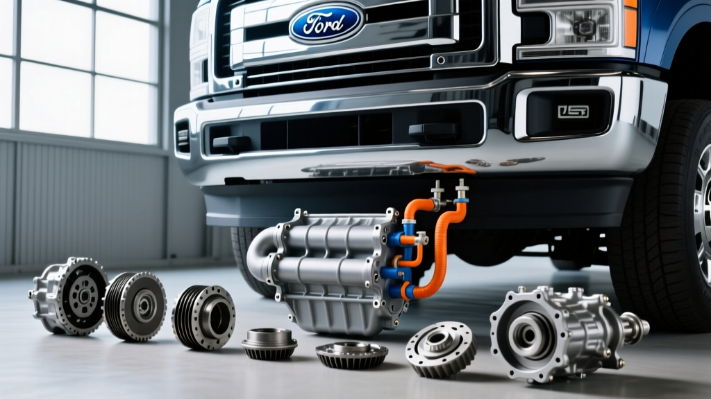
The secondary cooler is the traditional air-to-fluid heat exchanger. Its location is inside the Front Cooling Module (FCM), directly behind the front grille and bumper assembly. On trucks equipped with the Max Trailer Tow Package or heavy-duty snowplow prep packages, this auxiliary cooler is a massive, multi-pass plate-and-fin or tube-and-fin unit stacked in front of the radiator and intercooler. Airflow is forced through the FCM via the mechanical clutch fan and auxiliary electric puller fans.
| Generation | Transmission | Primary Cooler Location | Auxiliary Cooler Location | Total Fluid Capacity |
|---|---|---|---|---|
| 2011–2019 (Gen 1 & 2) | 6R140 (6-Speed) | Passenger Side Engine Block | Lower FCM Stack | 17.5 Quarts |
| 2020–2026 (Gen 3) | 10R140 (10-Speed) | Integrated Radiator / Block | Dedicated FCM Exchanger | 18.0 Quarts |
The Thermal Bypass Valve: The Hidden Bottleneck
You cannot discuss the 6.7 powerstroke transmission cooler location without addressing the thermal bypass valve. Located in the transmission cooling line circuit near the primary heat exchanger, this thermostatic valve dictates fluid routing.
- Cold Start (Below 180°F): The bypass valve remains closed, routing fluid only through the block-mounted fluid-to-fluid heat exchanger. The front auxiliary cooler is completely bypassed to allow the fluid to reach operating temperature quickly.
- Operating Temp (Above 180°F): The wax pellet inside the valve expands, opening the circuit to push fluid to the front-mounted auxiliary air-to-fluid cooler.
Diagnostic Edge Case: Many owners mistakenly believe their front auxiliary cooler is clogged or broken because it remains cold to the touch during light, unloaded driving in the winter. This is normal operation. However, if your transmission fluid temperature (TFT) exceeds 210°F under load and the auxiliary cooler lines remain cold, the thermal bypass valve is stuck closed. According to troubleshooting threads on Powerstroke.org, a stuck bypass valve is a leading cause of 6R140 clutch glazing during heavy towing.
OEM Failure Modes and Line Chafing
While the 6R140 and 10R140 are robust transmissions, the cooling lines routing from the transmission case to the block-mounted cooler and up to the FCM are vulnerable to specific failure modes.
1. Aluminum Line Chafing
The OEM hard lines are routed tightly along the passenger side frame rail and crossmembers. Over time, heavy engine torque (especially on tuned trucks producing over 600 lb-ft) causes drivetrain flex. The aluminum cooler lines can rub against the steel frame or transmission bellhousing brackets, wearing through the line and causing a catastrophic fluid dump. Inspecting the line isolation bushings every 30,000 miles is mandatory.
2. Plastic End-Tank Cracking (Auxiliary Cooler)
On earlier 2011–2014 models, the auxiliary cooler in the FCM utilized crimped plastic end-tanks. Extreme thermal cycling and road debris impact can cause these tanks to crack at the crimp collars, leading to slow leaks that coat the undercarriage in MERCON LV fluid.
Heavy-Duty Upgrades: Bypassing the Bottlenecks
If you are towing over 15,000 lbs through mountain passes, the OEM cooling stack may struggle to keep TFT below the 225°F danger zone. Upgrading the auxiliary cooling system is the most effective intervention. When selecting an aftermarket solution, you must decide between replacing the OEM front cooler or adding a remote-mounted auxiliary system.
Remote-Mounted Auxiliary Coolers
For extreme applications, brands like Derale and Mishimoto offer remote-mounted coolers that bypass the restrictive OEM FCM stack entirely. A popular setup involves mounting a high-capacity stacked-plate cooler (such as the Derale Series 9000 Plate-and-Fin Cooler) in the bed of the truck or behind the rear axle, utilizing an inline electric pump (like a Davies Craig EWP) to force fluid through the unit regardless of vehicle speed. This guarantees maximum cooling during low-speed, high-load scenarios like crawling up a steep grade.
Upgraded Front-Mounted Heat Exchangers
If you prefer to retain the OEM footprint, companies like Mishimoto and XDP offer direct-fit, all-aluminum replacement coolers that swap into the FCM. These units eliminate the weak plastic end-tanks and utilize dense, brazed stacked-plate cores that increase thermal transfer surface area by up to 40% over the OEM tube-and-fin design.
Pro-Tip for 10R140 Owners: The 10R140 requires Motorcraft MERCON ULV (Ultra Low Viscosity) fluid. Do NOT flush a 10R140 with standard MERCON LV or generic synthetic ATF. The ULV fluid is specifically engineered for the 10-speed's micro-valve body and torque converter lockup clutches. Using the wrong fluid will cause immediate shift flare and torque converter shudder.
Installation Torque Specs and Service Data
For DIY mechanics tackling a cooler replacement, line repair, or thermal bypass valve service, adhering to Ford's exact torque specifications is critical to prevent case stripping or line blowouts under high-line-pressure conditions (which can exceed 250 PSI in Tow/Haul mode).
- Cooler Line-to-Case Flare Nuts: 22 lb-ft (Use a backup wrench on the transmission case adapter to prevent twisting the internal seals).
- Block-Mounted Heat Exchanger Bolts: 89 lb-in (10 Nm). Do not overtighten; these thread directly into the aluminum engine block.
- Thermal Bypass Valve Housing: 18 lb-ft.
- FCM Auxiliary Cooler Mounting Brackets: 35 lb-ft.
- Fluid Fill Procedure: The 6R140 and 10R140 require a thermal fill procedure. You must fill the pan, run the engine until the TFT reaches exactly 185°F–193°F, and then check the fluid level at the transmission dipstick or overflow plug. Checking it cold will result in severe under-filling.
By understanding the intricacies of the 6.7 powerstroke transmission cooler location and the physics of the thermal bypass circuit, you can accurately diagnose overheating issues and select the right aftermarket cooling upgrades to keep your Super Duty on the road, not on the side of the highway. For more technical discussions on Ford diesel drivetrains, the Ford-Trucks.com forums remain an invaluable resource for real-world towing data and PID logging tutorials.