The Mechanical Handshake: Understanding the Core Duo
If you are diving into the world of manual transmissions, whether for a daily driver, a weekend track car, or a vintage muscle restoration, understanding the relationship between the clutch plate and pressure plate is your mandatory first step. While enthusiasts often obsess over engine horsepower, the drivetrain is where that power actually meets the pavement. If your clamping assembly is mismatched, the most powerful V8 in the world will simply turn your friction material into expensive smoke.
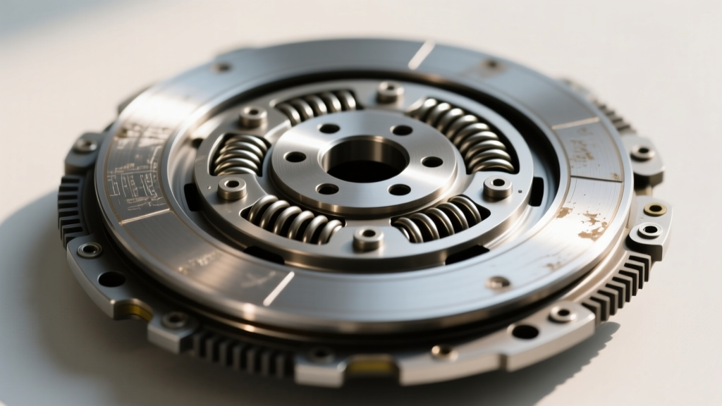
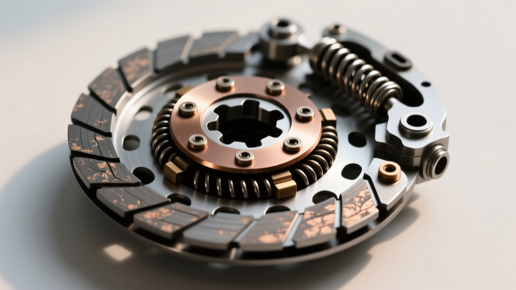
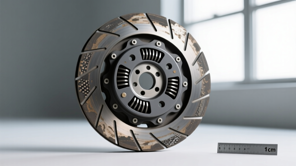
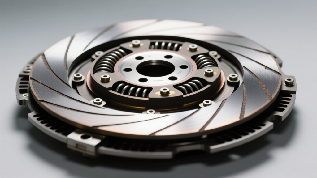
In simple terms, the flywheel is bolted to the engine's crankshaft and spins constantly. The clutch plate (often called the friction disc) is splined to the transmission input shaft. The pressure plate bolts directly to the flywheel, sandwiching the clutch plate between itself and the flywheel's friction surface. When you depress the pedal, the release bearing pushes against the pressure plate's fingers, lifting the clamping ring away from the clutch plate and interrupting power flow. When you release the pedal, the springs force the ring back down, locking the assembly together.
However, not all pressure plates are created equal. The spring mechanism, finger design, and metallurgy dictate your pedal feel, holding capacity, and high-RPM reliability. Let us break down the primary designs available on the market today.
Decoding Pressure Plate Types: Which Design Fits Your Build?
Selecting the right assembly requires looking past marketing jargon and understanding the mechanical architecture of the pressure ring. Here are the three dominant designs you will encounter.
1. Diaphragm Style (The Modern Standard)
The diaphragm pressure plate utilizes a single, large conical spring (the Belleville spring) that doubles as the release fingers. This is the undisputed standard for 95% of modern manual vehicles, from a Mazda MX-5 to a C8 Corvette manual swap.
The Advantage: Because the spring acts as a lever, pedal effort is relatively light and consistent. More importantly, at high RPM, centrifugal force pulls the diaphragm fingers outward, which actually increases the clamping load on the clutch plate. This prevents high-RPM slip without requiring a brutally stiff pedal at idle.
Example: The Centerforce Dual Friction series (e.g., part number DY336000 for GM LS applications) utilizes a patented centrifugal weight system on the diaphragm fingers to multiply clamping load by up to 40% at higher engine speeds, all while maintaining a stock-like pedal feel.
2. Borg & Beck (Multi-Finger / Coil Spring)
Step into a 1960s Mustang or a classic Mopar, and you will likely find a Borg & Beck style pressure plate. This design uses multiple heavy coil springs and three thick, distinct release fingers.
The Advantage: These offer massive, immediate clamping force right off idle, making them excellent for heavy-duty towing or low-RPM rock crawling.
The Drawback: At high RPM, the heavy coil springs and thick fingers experience extreme centrifugal pull. This fights against the release bearing, resulting in a pedal that becomes incredibly stiff and difficult to depress above 5,000 RPM. For a high-revving track car, this design is a liability.
3. Centrifugal Assist (Performance Hybrid)
Often confused with standard diaphragm plates, true centrifugal assist plates feature strategically placed tungsten or steel weights welded to the release fingers. As engine RPM climbs, the weights pull the fingers outward, mechanically levering the pressure ring tighter against the clutch plate.
This is the ultimate choice for high-horsepower street cars that still need to navigate stop-and-go traffic. You get the holding capacity of a racing clutch without the leg-cramping pedal effort required to compress 3,000 lbs of static spring pressure.
Application Matrix: Matching the Plate to Your Build
Use this comparison chart to narrow down your selection based on your vehicle's power output and intended use case.
| Pressure Plate Type | Spring Mechanism | Pedal Effort Profile | High-RPM Behavior | Ideal Application | Avg. Kit Cost (2026) |
|---|---|---|---|---|---|
| Standard Diaphragm | Single Belleville | Light to Moderate | Stable / Slight Increase | Daily driving, OEM replacement | $180 - $300 |
| Borg & Beck | Multiple Coil Springs | Moderate to Heavy | Extremely Heavy (Bind) | Vintage restorations, low-RPM towing | $250 - $450 |
| Centrifugal Assist | Weighted Belleville | Moderate (RPM dependent) | Clamping load increases | High-HP street/strip, forced induction | $400 - $750 |
| Racing Multi-Finger | High-Rate Coils | Extremely Heavy | Prone to bind without mods | Dedicated drag cars, circle track | $500 - $900 |
Flywheel Step Height: The Silent Killer of Clutch Kits
The most common reason a brand-new clutch plate and pressure plate assembly fails to disengage—or slips under load—is incorrect flywheel step height. The 'step' is the difference in elevation between the flywheel's friction surface (where the disc rides) and the mounting pad (where the pressure plate bolts down).
- Positive Step: The friction surface is raised above the mounting pad. (Common on GM LS engines, typically requiring 0.020' to 0.030').
- Negative Step: The friction surface is recessed below the mounting pad. (Found on many older Ford and import applications).
- Flat (Zero Step): Both surfaces are on the exact same plane. (Common on Ford 5.0L Coyote and many Honda applications).
If you mount a flat-step pressure plate onto a positive-step flywheel, the pressure ring will sit too high. The release bearing will run out of travel before it can fully lift the ring, resulting in a clutch that drags and grinds when shifting into gear. Always measure your flywheel step with a straight edge and feeler gauges before installation. According to McLeod Racing's technical guidelines, failing to verify step height accounts for nearly 30% of all warranty returns on performance clutch kits.
Torque Specifications and Fastener Science
Bolting the pressure plate to the flywheel is not a place for guesswork. The assembly is subjected to extreme harmonic vibrations and rotational shear forces. You must use the correct fasteners and a calibrated torque wrench.
GM LS Family (M8x1.25 Bolts)
For standard GM LS applications (LS1, LS3, LQ4), the OEM torque specification for the M8 pressure plate bolts is 35 lb-ft (47 Nm). If you upgrade to ARP fasteners (like ARP part #100-0701), you must use ARP Ultra-Torque lubricant and follow their specific rating, which is often slightly lower (around 25 lb-ft) due to the reduced friction of the lubricant and the higher tensile strength of the bolt.
Ford 5.0L Coyote (M8 Bolts)
On the Ford Coyote platform, the factory service manual dictates a torque spec of 29 lb-ft (39 Nm) for the pressure plate to flywheel bolts.
Pro-Tip: Never use an impact wrench to seat pressure plate bolts. You must thread them in by hand to avoid cross-threading the flywheel, then torque them down in a strict crisscross (star) pattern, gradually increasing the torque in three stages (e.g., 10 lb-ft, 20 lb-ft, final spec) to ensure the diaphragm spring seats evenly without warping the cover.
Common Beginner Mistakes to Avoid
'A clutch kit is only as good as the surface it clamps against and the alignment it receives during installation. Rushing the prep work guarantees a comeback.'
- Ignoring Spline Count: A GM T56 Magnum transmission uses a 26-spline input shaft, while an older Muncie M22 'Rock Crusher' uses a 10-spline. Buying a clutch plate with the wrong spline count is a costly, time-consuming error. Always count the splines on your input shaft before ordering.
- Skipping the Alignment Tool: If the clutch plate is not perfectly centered on the pilot bearing, the transmission input shaft will not slide through the disc hub. Forcing the transmission bellhousing against the block with the bellhousing bolts will bend the clutch plate hub and destroy the pilot bearing.
- Reusing a Glazed Flywheel: If your old clutch slipped, the flywheel surface is likely glazed or heat-checked. A new pressure plate cannot grip a glass-smooth surface. Always have the flywheel resurfaced on a rotary grinder or replaced with a new nodular iron or billet aluminum unit.
- Contaminating the Friction Material: Oils from your fingerprints, RTV silicone off-gassing, or a leaking engine rear main seal will ruin an organic or Kevlar clutch plate instantly. Wipe the flywheel surface with brake cleaner and a lint-free cloth immediately before mating the components.
Final Thoughts on Drivetrain Synergy
Upgrading your manual transmission setup is an exercise in balance. The goal is to select a clutch plate and pressure plate combination that provides adequate holding capacity for your engine's torque output while maintaining the drivability your chassis requires. By understanding the mechanical differences between diaphragm and Borg & Beck designs, respecting flywheel step heights, and adhering to precise torque specifications, you will build a drivetrain that hooks hard, shifts smoothly, and survives the abuse of the street and track.