The Anatomy of Intermittent Fan Clutch Failures in Class 8 Trucks
In the modern heavy-duty trucking industry, thermal management is a highly calibrated science. For Class 8 owner-operators and fleet technicians in 2026, an intermittent fan clutch failure on a Peterbilt chassis is more than just a nuisance—it is a critical fault that can trigger severe engine derates, destroy AC compressors, and lead to catastrophic overheating on grades. Unlike manual transmission clutches that suffer from friction disc wear and hydraulic slave cylinder leaks, the Peterbilt fan clutch operates at the intersection of pneumatics, multiplexed electrical networks, and high-RPM mechanical rotation.
When a driver reports that the fan clutch 'sometimes works and sometimes doesn't,' the diagnostic path requires a systematic isolation of the air supply, the electrical control circuit, and the mechanical friction assembly. Whether you are working on a PACCAR MX-13, a Cummins X15, or a Navistar A26 engine, understanding the fail-safe logic of the fan clutch is the first step toward an accurate diagnosis.
Fail-Safe Logic: Normally Open vs. Normally Closed Systems
Before probing any wiring harnesses, you must identify the operational logic of the specific fan clutch installed on your Peterbilt. Most modern heavy-duty applications utilize a spring-engaged, air-disengaged (Normally Open) design. In this fail-safe setup, internal spring pressure locks the friction liner to the drive sheave, engaging the fan. When the Engine Control Module (ECM) determines that cooling is not required, it energizes a solenoid valve to route 90-120 PSI of air into the clutch chamber, compressing the spring and disengaging the fan to save fuel and reduce parasitic drag.
If your Peterbilt is experiencing intermittent overheating, the clutch is failing to engage (loss of spring tension, mechanical binding, or false air pressure). If the truck is experiencing intermittent roaring, fuel mileage drops, and sluggish acceleration, the clutch is failing to disengage (stuck solenoid, air leaks, or clogged exhaust ports).
Diagnostic Matrix: Symptoms and Root Causes
Use the following matrix to narrow down the root cause based on the driver's specific complaint and the operating conditions present when the failure occurs.
| Reported Symptom | Operational State | Probable Root Cause | Primary Diagnostic Test |
|---|---|---|---|
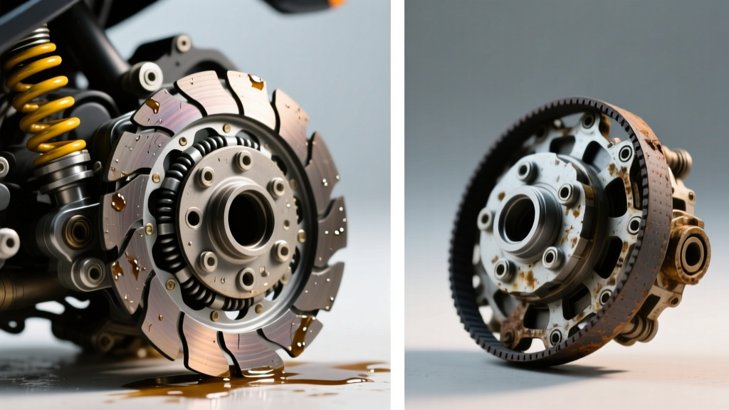
| Random overheating at idle/low speed | Fails to Engage | Worn friction lining, broken internal spring, or oil contamination on the friction surface. | Visual inspection of friction pad; measure air gap with feeler gauge. |
| Intermittent loud roaring on highway | Fails to Disengage | Chafed J1939 datalink wire, failing ECM driver, or stuck pneumatic solenoid valve. | Scan for active SPN codes; test solenoid coil resistance (typically 10-15 ohms). |
| Delayed engagement under heavy load | Sluggish Response | Clogged air filter/regulator on the fan clutch air line, or restricted wet-tank air supply. | Install inline pressure gauge to verify 90+ PSI at the clutch air fitting. |
| AC compressor clutch cycling rapidly | Thermal Override Fault | High-side AC pressure sensor sending erratic PWM signals to the ECM. | Monitor AC pressure PID via diagnostic software (e.g., Davie4 or Cummins INSITE). |
Pneumatic Circuit Diagnostics: Chasing Air Leaks and Pressure Drops
The most common culprit behind intermittent Peterbilt fan clutch disengagement issues is a degradation in the pneumatic supply. Heavy-duty truck air systems are notorious for carrying moisture, compressor oil mist, and desiccant dust into the secondary air circuits that feed the fan clutch solenoid.
Testing the Air Supply and Regulator
Locate the fan clutch air filter and pressure regulator, typically mounted on the firewall or near the steering gear box. Over time, the sintered bronze filter element becomes saturated with compressor oil, restricting airflow. This causes a delayed disengagement, meaning the fan stays on longer than necessary, robbing horsepower and fuel economy.
- Step 1: Disconnect the air supply line at the solenoid valve and install a 0-160 PSI inline pressure gauge.
- Step 2: With the engine running and the AC turned off, verify that the supply pressure reads between 110 and 120 PSI. If it reads below 90 PSI, the regulator is failing or the upstream filter is clogged.
- Step 3: Command the fan clutch OFF using a diagnostic laptop. The gauge should drop to 0 PSI immediately. If the pressure bleeds down slowly (taking more than 2-3 seconds), the solenoid exhaust port is obstructed by carbon buildup or ice crystal formation in winter months.
For replacement, always use OEM-spec components. A standard Horton air filter/regulator kit (Part #830000 series) or a Kit Masters service kit will resolve 40% of all intermittent pneumatic faults on Peterbilt 579 and 389 models.
Electrical and Multiplexing Faults: Probing the ECM and Solenoid
Modern Peterbilt chassis utilize a complex J1939 multiplexed electrical network. The ECM does not simply turn the fan clutch 'on' and 'off'; it often uses a Pulse Width Modulated (PWM) signal to slip the clutch slightly, providing proportional cooling based on exact coolant temperature, intake manifold temperature, and AC head pressure.
Solenoid Coil and Wiring Harness Testing
Intermittent electrical faults are notoriously difficult to pinpoint because they often manifest only when the harness is hot or subjected to chassis vibration. According to Peterbilt's official support portal, technicians should avoid piercing wires with test lights, which introduces corrosion into the harness.
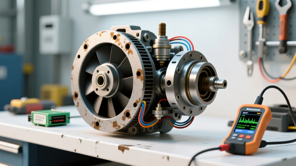
- Resistance Check: Disconnect the 2-pin Deutsch connector at the fan clutch solenoid. Measure the resistance across the solenoid pins. A healthy Horton or Kysor solenoid should read between 11.0 and 15.0 ohms at room temperature. An open circuit (OL) indicates a broken internal winding, while a reading below 8 ohms suggests a short.
- Voltage Drop Test: Back-probe the harness side of the connector with a digital multimeter (DMM). With the key ON and engine OFF, command the fan ON via your scan tool. You should see a solid 12V reference (or a varying PWM duty cycle depending on the ECM calibration). If the voltage fluctuates wildly while wiggling the harness near the battery box ground stud, you have identified a chafed wire or corroded chassis ground.
- J1939 Datalink Interference: If the fan clutch roars on and off randomly while the cruise control surges, suspect a terminating resistor failure on the J1939 backbone. A faulty 120-ohm terminator can cause the ECM to receive corrupted AC pressure data, triggering erratic fan clutch overrides.
Mechanical Wear: Friction Linings, Bearings, and Torque Specs
If the electrical and pneumatic systems test perfectly, the intermittent fault lies within the mechanical rotating assembly. Fan clutches endure immense centrifugal forces and harmonic vibrations. Over 500,000 miles, the internal friction linings glaze, and the pilot bearings develop radial play.
Inspecting the Friction Surface and Air Gap
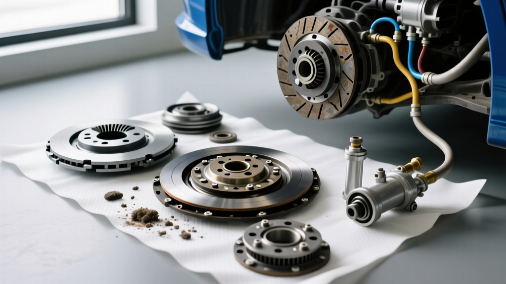
Slide a bright flashlight behind the fan blade and inspect the friction liner on the drive sheave. If the liner is glazed, cracked, or missing chunks, the clutch will slip intermittently under high thermal loads, failing to pull adequate CFM through the charge air cooler and radiator. Furthermore, check the air gap between the armature and the electromagnet/pneumatic piston face. While specific tolerances vary by manufacturer, Horton's heavy-duty fan clutch documentation generally specifies an air gap between 0.015 and 0.030 inches. If the gap exceeds 0.045 inches, the magnetic or pneumatic force is insufficient to fully lock the clutch, resulting in intermittent slippage and overheating.
Bearing Play and Hub Torque Specifications
Grab the fan blade at the 12 and 6 o'clock positions and attempt to rock it. Any discernible clunk or radial play indicates a failed fan hub pilot bearing. A worn bearing allows the armature to wobble, causing intermittent contact and rapid destruction of the friction liner.
When replacing the fan clutch assembly or the fan hub, adhering to precise torque specifications is non-negotiable. For most Peterbilt applications utilizing a standard 4-bolt or 6-bolt fan hub mounting pattern:
- Fan Hub to Engine Front Cover Bolts: Torque to 130-150 lb-ft (verify specific PACCAR/Cummins service manual).
- Fan Blade to Clutch Sheave Bolts: Torque to 45-55 lb-ft, always applying medium-strength blue threadlocker (e.g., Loctite 243) to prevent harmonic loosening.
- Air Line Fittings: Use only DOT-approved push-to-connect fittings and torque threaded brass elbows to 15-20 lb-ft to avoid cracking the solenoid housing.
Advanced Thermal Derate Diagnostics (SPN Codes)
In 2026, engine protection strategies are more aggressive than ever. If your intermittent fan clutch issue goes unresolved, the ECM will initiate a thermal derate to save the engine block and cylinder head. You will likely encounter the following Society of Automotive Engineers (SAE) J1939 Suspect Parameter Numbers (SPNs):
- SPN 110 FMI 18 (Engine Coolant Temperature - Data Valid but Below Normal/High): The ECM detects coolant temps exceeding 225°F and begins to limit fuel delivery. This is your primary indicator that the fan clutch is failing to engage or the radiator is externally fouled.
- SPN 100 FMI 18 (Engine Oil Pressure - Low): As oil temperatures soar due to lack of airflow through the oil cooler, oil viscosity drops, triggering a low oil pressure fault. This is a secondary symptom of a failed fan clutch.
- SPN 708 FMI 5 (Fan Clutch Solenoid - Current Below Normal): The ECM has detected an open circuit in the solenoid wiring. This confirms an electrical break, often found at the weatherpack connector near the front of the oil pan.
For deep-dive electrical schematics and OEM troubleshooting trees, technicians frequently rely on Diesel Laptops technical resources to cross-reference OEM fault codes with aftermarket component testing procedures.
Summary: A Systematic Approach to Intermittent Faults
Diagnosing an intermittent Peterbilt fan clutch requires moving beyond simple visual inspections. By systematically verifying the pneumatic supply pressure, testing the solenoid resistance and PWM signals, and measuring the mechanical air gap and bearing play, you can isolate the root cause with surgical precision. Whether the fault lies in a $15 clogged air filter regulator or a failing ECM driver board, applying this structured diagnostic protocol will eliminate the guesswork, prevent unnecessary parts swapping, and keep Class 8 trucks running cool and profitable on the highway.