The Hidden Geometry: Why Master Cylinder Location Dictates Pedal Feel
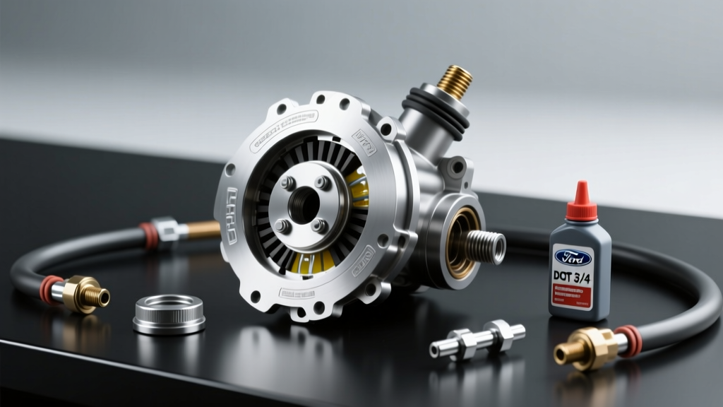
When building a high-performance manual drivetrain—whether you are swapping a Coyote V8 with a Tremec T56 Magnum F or rebuilding a track-dedicated Porsche G50—the hydraulic system is often the weakest link. Enthusiasts frequently obsess over clutch disc friction materials and pressure plate clamp loads, yet completely ignore the foundational geometry of the actuation system. Understanding the exact location of the clutch master cylinder is the critical first step in diagnosing poor pedal feel, incomplete disengagement, and premature seal failure in high-torque applications.
In a performance context, the master cylinder is not just a fluid pump; it is the primary multiplier of your pedal ratio. Most performance chassis utilize a pedal ratio between 6:1 and 7:1. If the mounting location forces an awkward pushrod angle, or if the firewall flexes under the immense load of a 3,200-lb clamp load pressure plate, your effective hydraulic ratio degrades. This results in a spongy pedal, gear rattle in neutral, and catastrophic synchro wear in transmissions like the ZF S6-650.
Firewall Flex and Parasitic Loss
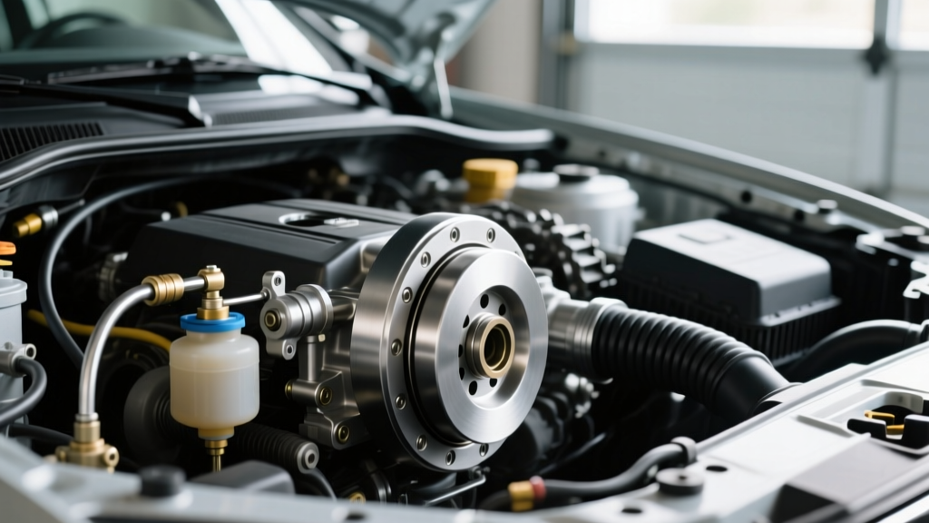
The most common OEM location for the master cylinder is directly on the sheet-metal firewall. While adequate for a stock 1,800-lb clamp load single-disc setup, this location becomes a liability in performance builds. When you depress the pedal against an Exedy or McLeod twin-disc clutch, the firewall can deflect rearward by 2mm to 4mm. This deflection alters the static location of the clutch master cylinder relative to the pedal pushrod, absorbing pedal travel that should be moving the slave cylinder. The diagnostic symptom is a pedal that feels firm initially but 'falls away' or fails to fully disengage the clutch under maximum load.
Diagnosing Pushrod Bind: The Silent Killer of Clutch Hydraulics
If the location of the clutch master cylinder dictates a pushrod angle exceeding 3 degrees off-axis relative to the piston bore, you will experience accelerated internal seal wear. OEM and aftermarket cylinders rely on EPDM or Viton internal cups to maintain hydraulic pressure. An angular misalignment causes the pushrod to cock the piston slightly inside the bore.
- Asymmetric Seal Wear: The piston rides on one side of the bore, wearing the seal lip and allowing fluid to bypass internally.
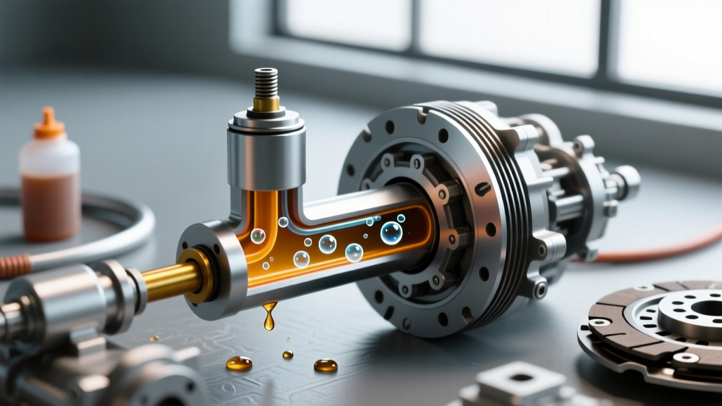
- Return Port Blockage: Misalignment can prevent the piston from fully returning to the resting position, keeping the compensating port partially blocked. This leads to hydraulic pressure buildup as the fluid heats up, causing the clutch to slip without the driver touching the pedal.
- Pedal Bind: Physical friction against the pushrod boot and firewall grommet, resulting in a notchy pedal return.
Diagnostic Test: Disconnect the pushrod from the pedal arm. Cycle the pushrod into the master cylinder by hand. If you feel lateral resistance or binding before the piston engages, your mounting location and pedal arm geometry are misaligned. The fix requires either shimming the master cylinder mounting studs or utilizing an adjustable spherical rod end (heim joint) at the pedal connection to eliminate side-loading.
Bore Sizing vs. Clamping Force Requirements
Diagnosing a heavy pedal or inadequate release bearing travel often comes down to a mismatch between the master cylinder bore size and the slave cylinder volume requirements. According to Tremec's official T56 Magnum documentation, the internal hydraulic release bearing (HRB) typically requires 0.500 to 0.550 inches of total stroke to fully disengage the clutch fingers. If your bore is too large, you gain pressure but lose stroke volume; if it is too small, you gain stroke but the pedal effort becomes unbearable.
| Master Cylinder Bore | Volume per 1" Stroke | Ideal Clamp Load Range | Pedal Effort (at 6:1 Ratio) | Best Application |
|---|---|---|---|---|
| 3/4" (0.750") | 0.441 cu in | 1,800 - 2,400 lbs | Low (25-35 lbs) | OEM replacements, light single-disc |
| 7/8" (0.875") | 0.601 cu in | 2,400 - 3,200 lbs | Medium (40-55 lbs) | Performance twin-disc, T56 Magnum |
| 1" (1.000") | 0.785 cu in | 3,200 - 4,500+ lbs | High (60+ lbs) | Triple-disc, heavy-duty drag/track |
Note: Always verify the specific slave cylinder bore size. A larger master cylinder bore pushing a small slave bore will result in excessive pedal travel and potential bottoming out of the slave piston.
Step-by-Step Diagnosis: From Reservoir to Slave Cylinder
When diagnosing a failing hydraulic system in a performance vehicle, follow this systematic isolation process to determine if the fault lies in the master cylinder location, the lines, or the slave assembly.
1. Static Pedal Height and Freeplay Check
Measure the pedal freeplay. Performance setups should have minimal freeplay (1/8" to 1/4" at the pedal pad). Excessive freeplay indicates a worn pushrod clevis pin or an incorrectly adjusted master cylinder location depth. Torque the pushrod clevis pin nut to 10-12 lb-ft and secure with a fresh cotter pin.
2. The Hose Clamp Isolation Test
If the pedal drops to the floor under sustained pressure, use a specialized hose clamp tool to pinch off the flexible rubber hose connecting the hard line to the slave cylinder (if applicable). If the pedal holds firm while clamped, the master cylinder and location geometry are sound, and the leak is downstream (slave cylinder or HRB). If the pedal still drops, the master cylinder internal seals are bypassing.
3. Thermal Breakdown Analysis
Performance clutches generate immense heat, which transfers through the bellhousing and hydraulic lines. Standard DOT 3 fluid boils at 401°F (205°C). In a track environment, localized boiling creates compressible gas pockets. Upgrade to a high-performance fluid like Castrol SRF (590°F / 310°C dry boiling point) or Motul RBF 600 to eliminate vapor lock.
Upgrade Paths: Remote Reservoir and Bore Swaps
If the diagnosis confirms that the OEM firewall location is causing flex, pushrod bind, or clearance issues with aftermarket exhaust headers or brake boosters, transitioning to a remote-mounted master cylinder is the ultimate performance solution.
According to Wilwood Engineering's clutch master cylinder catalog, their tandem and single remote reservoir setups allow you to mount the cylinder low on the chassis rail or inner fender, completely eliminating firewall flex. The Wilwood 7/8" Bore Master Cylinder (Part #260-1304) retails for approximately $130-$150 and features a hard-anodized aluminum bore that resists the micro-pitting common in cast-iron OEM units.
For dedicated track cars, Tilton Racing's hydraulic system technical guides recommend their 78-Series 3/4" or 7/8" Master Cylinders with integrated remote reservoirs ($280-$320). These units utilize Viton seals specifically designed to withstand the aggressive chemical composition of high-temperature racing brake fluids and the extreme vibration of unsprung chassis locations.
Hard Line vs. AN3 Braided Upgrades
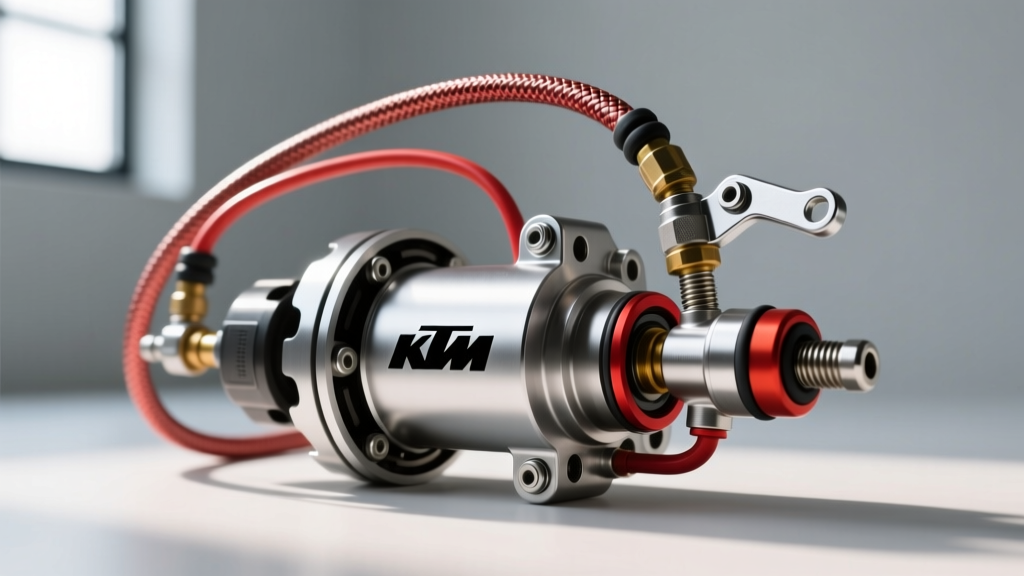
When relocating the master cylinder, abandon OEM rubber flex lines. Rubber lines expand under the 1,200+ PSI generated during a heavy clutch release, robbing you of precise modulation. Upgrade to AN3 stainless steel braided lines with Teflon (PTFE) inner cores. Expect to spend $60-$90 for custom-length AN3 lines. Ensure all AN fittings are torqued to 12-15 lb-ft using an aluminum AN wrench to prevent rounding the hex nuts.
Expert Bleeding Tip: When dealing with a relocated master cylinder that sits lower than the slave cylinder, gravity bleeding is ineffective due to trapped air pockets in the upward-sloping lines. You must use a pressure bleeder set to 15-20 PSI at the master reservoir, combined with a vacuum bleeder at the slave cylinder nipple, to force the micro-bubbles out of the system. Always bench-bleed the master cylinder before installation to save hours of frustration.
Final Torque Specs and Installation Checklist
When finalizing your master cylinder location and upgrade, adhere to these critical fastener specifications to ensure safety and longevity:
- Master Cylinder Mounting Nuts (Firewall/Studs): 15-18 lb-ft (Use a reinforcing plate if exceeding 18 lb-ft on sheet metal).
- Pushrod Clevis Pin: 10-12 lb-ft (Must use castellated nut and cotter pin).
- AN3 Hydraulic Line Fittings: 12-15 lb-ft (Use PTFE tape or liquid thread sealant only on NPT adapters, never on AN flare seals).
- Slave Cylinder / HRB Mounting Bolts: 18-22 lb-ft (Apply medium-strength blue threadlocker to prevent vibration-induced backing out).
By critically evaluating the location of the clutch master cylinder and upgrading the bore sizing to match your specific transmission and clutch assembly, you transform a vague, unreliable pedal into a precise, communicative interface that protects your drivetrain investment.