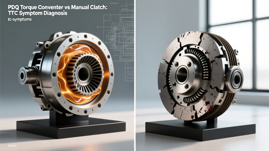
When diagnosing drivetrain shudder, slip, or chatter, the line between a failing manual friction clutch and an automatic Torque Converter Clutch (TCC) can easily blur. Both systems serve the fundamental purpose of mechanically coupling the engine's rotational force to the transmission input shaft. However, their operational physics, failure modes, and diagnostic pathways are vastly different. This distinction becomes especially critical when evaluating heavy-duty aftermarket upgrades, such as a multi-plate billet PDQ torque converter, against traditional manual setups like a South Bend or LuK clutch kit.
In this technical deep-dive, we will dissect the mechanical differences between manual friction clutches and automatic TCC lockup mechanisms. We will explore how to accurately read OBD-II PID data to isolate TCC slip, identify the unique failure symptoms of heavy-duty PDQ torque converters, and provide a concrete diagnostic framework to separate torque converter shudder from manual clutch chatter.
The Physics of Slip: Fluid Coupling vs. Friction Plates
To understand the symptoms, we must first understand the engagement mechanics. A traditional manual clutch relies on a diaphragm spring, a heavy cast-iron pressure plate, and a single or dual friction disc sandwiched against a steel flywheel. Engagement is binary and mechanically aggressive; clamping force is measured in thousands of pounds, and slip is entirely dependent on pedal modulation and friction material degradation.
Conversely, a torque converter is primarily a fluid coupling device utilizing a pump, turbine, and stator. To eliminate the inherent parasitic loss of fluid slip at highway speeds, modern automatics employ a Torque Converter Clutch (TCC). When the TCC engages, a hydraulic piston pushes a friction-lined plate against the inner surface of the converter cover, creating a 1:1 mechanical lock. In high-performance or heavy-duty applications, a PDQ torque converter elevates this design by utilizing a multi-plate clutch pack and a billet steel cover to handle the immense torque output of diesel engines like the Cummins 6.7L or Duramax L5P.
Key Mechanical Distinctions
- Clamping Force Source: Manual clutches use mechanical spring pressure; TCCs use regulated hydraulic line pressure (typically 80-150 PSI depending on the transmission and load).
- Friction Material: Manual clutches use organic, Kevlar, or sintered iron compounds designed for high-heat dry engagement. TCCs use carbon-impregnated paper, woven Kevlar, or sintered bronze designed to operate submerged in automatic transmission fluid (ATF).
- Slip Tolerance: Manual clutches must achieve zero slip to prevent catastrophic heat failure. Modern TCCs often operate with a 'controlled micro-slip' (10-30 RPM) managed by the Transmission Control Module (TCM) to dampen torsional engine vibrations.
Symptom Overlap: When TCC Shudder Mimics Clutch Chatter
The most common diagnostic trap occurs when a customer reports a 'shuddering' or 'chattering' sensation during acceleration. A manual clutch chatter usually occurs during initial takeoff (1st gear engagement) and is caused by oil contamination, hot spots on the flywheel, or broken damper springs in the clutch disc. It is a low-speed, high-torque phenomenon.
TCC shudder, however, typically manifests at steady-state cruising speeds (45-65 MPH) in higher gears (4th, 5th, or 6th). It feels like driving over a series of shallow rumble strips. However, when a heavy-duty PDQ torque converter begins to experience lockup issues, the sheer mass of the drivetrain can make this shudder feel deceptively similar to a manual clutch failing to engage.
Diagnostic Data Table: TCC Slip vs. Manual Clutch Slip
| Diagnostic Parameter | Manual Clutch Failure | TCC Lockup Failure (e.g., PDQ Unit) |
|---|---|---|
| Primary Operating Condition | Takeoff, WOT, or high-load low-speed pulling | Steady-state cruise (45-75 MPH), light-to-medium throttle |
| Tachometer Behavior | RPMs climb disproportionately to vehicle speed | RPMs fluctuate rapidly (surge 50-200 RPM) or fail to drop upon lockup |
| Scanner PID Data | N/A (No electronic clutch slip sensor) | 'TCC Slip Speed' PID shows >40 RPM variance when locked |
| Common DTCs | None (Mechanical failure) | P0741, P0742, P2763, P0744 |
| Fluid/Smell Indicators | >Burnt asbestos/organic smell from bellhousing inspection coverDark, burnt-smelling ATF; loss of friction modifiers |
Deep-Dive Diagnostics: Reading TCC Slip on OBD-II Scanners
Unlike a manual clutch, which requires physical inspection or road-load testing to diagnose, the TCC is heavily monitored by the vehicle's TCM. When diagnosing a suspected PDQ torque converter issue in a GM 6L80 or Ford 6R80, the most critical PID (Parameter Identification) data point is TCC Slip Speed.
TCC Slip Speed is calculated by subtracting the Transmission Input Shaft Speed (TISS) from the Engine RPM. When the TCM commands the TCC solenoid to '100% Duty Cycle' (fully locked), the slip speed should drop to near zero (typically between -10 and +20 RPM to account for sensor noise and micro-slip programming).
Interpreting the Data
- Normal Operation: Commanded TCC state is 'ON', Actual TCC Slip is 15 RPM.
- Friction Material Degradation: Commanded TCC state is 'ON', Actual TCC Slip bounces erratically between 40 and 150 RPM. This indicates the carbon or Kevlar lining inside the PDQ converter is glazed or worn, and the TCM is rapidly pulsing the PWM (Pulse Width Modulation) solenoid to maintain grip, causing the physical shudder.
- Hydraulic Circuit Leak: Commanded TCC state is 'ON', Actual TCC Slip is a steady 250+ RPM. This points to a leak in the stator support tube, a worn TCC apply valve bore in the valve body, or low line pressure, rather than a failure of the torque converter itself.
According to Sonnax Technical Resources, continuous TCC slip not only destroys the friction lining but also generates immense heat, which is transferred directly into the transmission fluid, degrading the entire hydraulic system. If you observe steady-state slip exceeding 100 RPM, immediate intervention is required to prevent transmission burnout.
PDQ Torque Converter Lockup Mechanisms: Heavy-Duty Applications
When upgrading a diesel truck, the factory torque converter is often the weakest link. The stamped steel cover of an OEM converter will physically flex (balloon) under the immense torque of a tuned Cummins or Duramax, preventing the TCC piston from applying even clamping pressure. This flex causes severe chatter and premature friction material failure.
This is where a PDQ torque converter shines. PDQ units utilize a billet steel cover that is machined from a single block of steel, eliminating flex entirely. Furthermore, they often employ a 3-disc or 4-disc multi-plate TCC clutch pack. By dividing the torque load across multiple friction surfaces, the clamping pressure required per plate is drastically reduced, allowing for smooth, chatter-free lockup even at 800+ lb-ft of torque.
Specific Failure Modes in Billet PDQ Units
Because the billet cover and multi-plate clutch pack are virtually indestructible under normal use, when a PDQ torque converter exhibits symptoms, the root cause is almost always external:
- Friction Modifier Depletion: Heavy-duty diesels generate massive heat. If the ATF (such as Dexron VI or TES 295) is not changed at proper intervals, the friction modifiers burn off. The TCC material loses its 'grab-and-hold' characteristic, resulting in a violent shudder that mimics a warped manual flywheel.
- Stator Support Tube Wear: The hydraulic fluid that applies the TCC piston travels through the inner and outer journals of the stator support tube. If the transmission's input shaft bushings wear out, the shaft wobbles, scoring the support tube and bleeding off TCC apply pressure.
- PWM Solenoid Fatigue: The solenoid regulating the lockup pressure can stick or fail to achieve full duty cycle, leading to P2763 (Torque Converter Clutch Pressure Control Circuit High) codes.
For further reading on hydraulic circuit diagnostics and solenoid behavior, Transmission Digest regularly publishes case studies on PWM solenoid degradation in high-mileage heavy-duty applications.
Cost and Replacement Realities (2026 Market Data)
Understanding the financial implications of these repairs is crucial for accurate customer counseling. Replacing a manual clutch and replacing an automatic torque converter involve vastly different labor scales and part costs.
Manual Clutch Replacement (e.g., G56 Transmission)
- Parts: Heavy-duty clutch kit (South Bend or LuK): $700 - $1,400
- Flywheel Resurfacing/Replacement: $250 - $800
- Labor: 6.0 - 9.0 hours (Requires dropping the entire manual transmission, transfer case, and crossmembers)
- Total Estimated Cost: $1,800 - $3,500
PDQ Torque Converter Replacement (e.g., Allison 1000 or 68RFE)
- Parts: Billet Multi-Plate PDQ Torque Converter: $950 - $1,600
- Fluid & Filters: 12-14 quarts of synthetic ATF + deep pan filter: $250 - $400
- Labor: 7.0 - 11.0 hours (Requires R&R of the automatic transmission, cooler line flushing, and TCM reflash/adaptation)
- Total Estimated Cost: $2,200 - $4,100
Note: When replacing a torque converter due to friction material failure, a mandatory inline cooler flush is required. Failure to flush the transmission cooler will result in trapped clutch debris circulating through the valve body, causing immediate solenoid failure upon reassembly.
Final Diagnostic Takeaways
While a manual clutch and a torque converter clutch share the same end goal—mechanical coupling—their diagnostic signatures are entirely distinct. Manual clutch failures are characterized by load-based slip, takeoff chatter, and a lack of electronic oversight. TCC failures, particularly in robust aftermarket units like the PDQ torque converter, are characterized by steady-state cruise shudder, erratic OBD-II slip PIDs, and hydraulic or friction-modifier deficiencies.
By relying on TCC Slip Speed data rather than 'seat-of-the-pants' feel, technicians can accurately separate a failing lockup piston from a failing PWM solenoid or degraded fluid. Always verify the integrity of the stator support tube and valve body TCC apply circuits before condemning a billet torque converter, as the converter is often the victim of a hydraulic leak, not the source of the failure.
For more diagnostic flowcharts regarding P0741 and P0742 torque converter clutch circuit codes, refer to the OBD-Codes P0741 Troubleshooting Guide.