Decoding the Motorcycle Clutch Diagram: The Blueprint for Diagnostics
Unlike the dry, single-plate clutches found in most automotive manual transmissions, the vast majority of motorcycles utilize a wet, multi-plate clutch system bathed in engine oil. When diagnosing slip, drag, or chatter, referencing a precise motorcycle clutch diagram is not just helpful—it is mandatory. The diagram maps the critical stack order, the interaction between the clutch basket and inner hub, and the actuation mechanism. As of 2026, with modern sintered bronze and advanced Kevlar friction materials becoming standard on high-performance machines, tolerances are tighter than ever. This technical deep-dive provides a comprehensive clutch system inspection checklist, complete with OEM-level measurements, torque specifications, and diagnostic frameworks.
Phase 1: External Actuation & Hydraulic/Cable Inspection
Before cracking the right-side crankcase cover, you must isolate the actuation system. A poorly adjusted cable or a spongy hydraulic line will mimic the symptoms of worn friction plates or warped steels.
Cable-Actuated Systems
- Free Play Measurement: Measure 10mm to 15mm of free play at the lever's ball end. This ensures the clutch pushrod is fully retracted, allowing the pressure plate to clamp completely.
- Cable Friction Check: Disconnect the cable at the engine actuator arm. The lever should move with zero resistance. If it binds, the PTFE liner is compromised, and the cable must be replaced.
Hydraulic-Actuated Systems
- Fluid Degradation: Brake fluid (DOT 4 or DOT 5.1) is hygroscopic. If the fluid in the master cylinder reservoir is dark or cloudy, moisture has contaminated the system, lowering the boiling point and causing internal seal swelling.
- Master Cylinder Bore Wear: If the lever feels 'squishy' even after bleeding, inspect the master cylinder bore for longitudinal scoring. According to Motorcyclist Online, rebuilding the master cylinder with a new piston and seal kit (often under $40) is more cost-effective than replacing the entire unit.
Phase 2: Internal Teardown & Visual Diagnostics
Drain the engine oil and remove the right-side crankcase cover. Keep a magnetic tray nearby; the clutch pushrod bearing (often a tiny 9/16-inch needle or ball bearing) is notorious for falling into the engine cases upon disassembly.
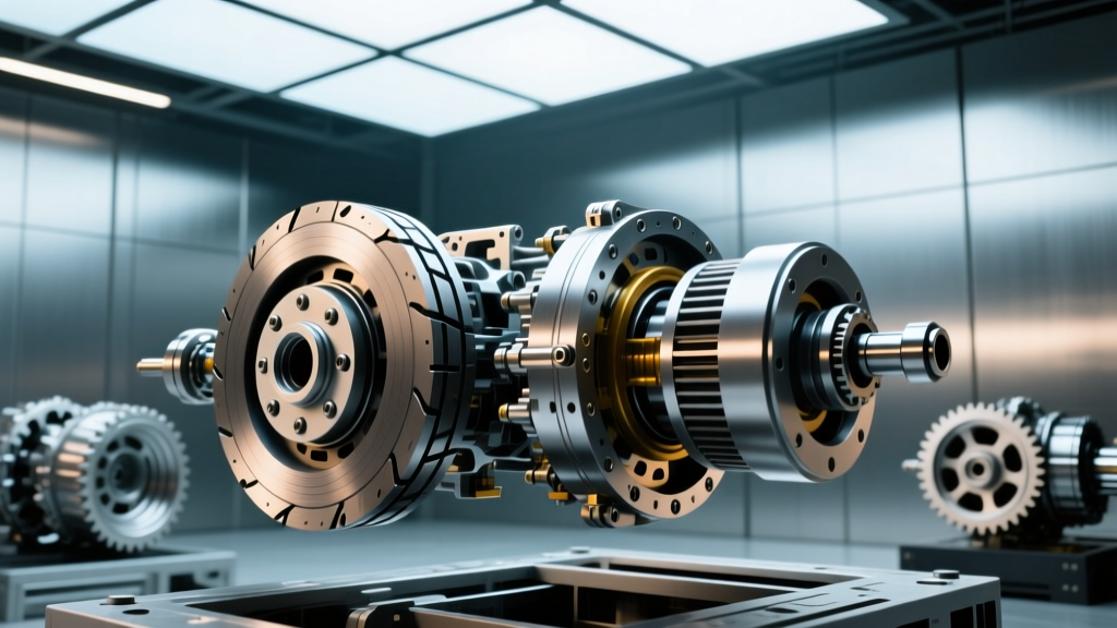
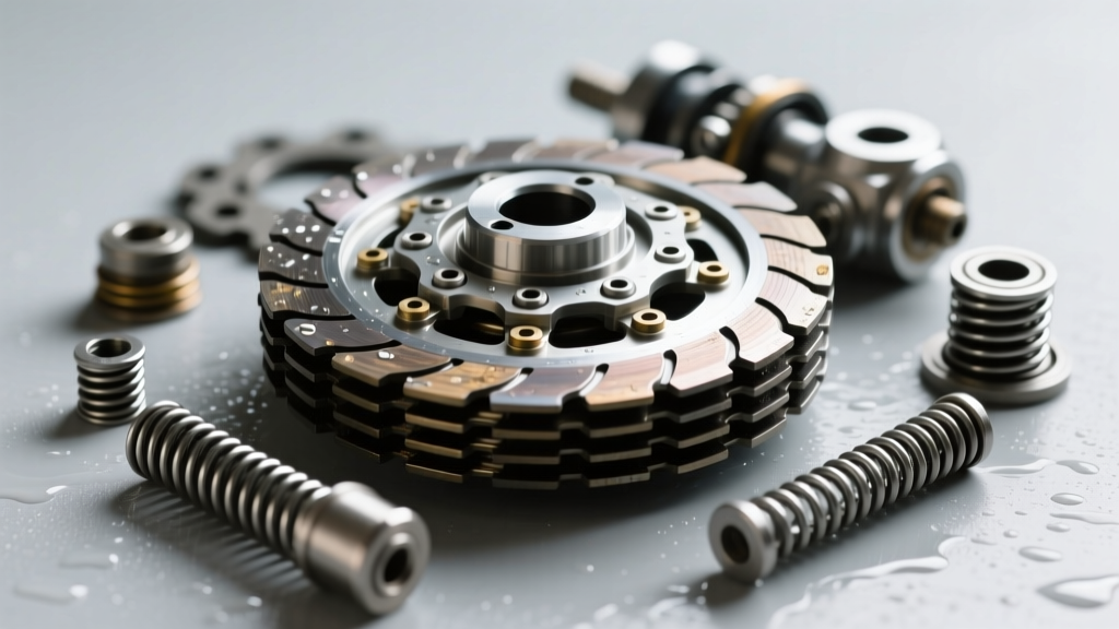
Consult your specific motorcycle clutch diagram to identify the lifter plate, pressure springs, and the alternating stack of friction and steel plates. Remove the pressure plate bolts in a crisscross pattern to prevent warping the aluminum lifter.
Clutch Basket and Inner Hub Notching
The most common cause of a motorcycle failing to find neutral or exhibiting severe 'clutch drag' is basket notching. The aluminum tangs of the outer basket and the steel splines of the inner hub deform over time under high-torque loads.
- The Fingernail Test: Run your fingernail across the tangs of the outer basket. If your nail catches in a divot deeper than 0.2mm, the plates cannot slide freely when the lever is pulled. This causes drag and false neutrals.
- Remediation: Minor notching can be carefully filed flat using a fine-grit flat file. Severe notching requires basket replacement or upgrading to a billet aluminum aftermarket unit with dampened rubber inserts.
Phase 3: Metallurgical Inspection & Tolerance Table
Once the stack is removed, you must measure every component. Do not rely on visual inspection alone for friction plate thickness or steel plate warpage. Use a micrometer for friction plates and a feeler gauge on a machined flat surface for the steels.
| Component | OEM Specification | Service Limit | Diagnostic Tool |
|---|---|---|---|
| Friction Plate Thickness | 2.92 - 3.08 mm | 2.60 mm | Outside Micrometer |
| Steel Plate Warpage | 0.00 mm (Dead Flat) | 0.10 mm | Feeler Gauge & Surface Plate |
| Clutch Spring Free Length | 45.50 mm | 43.20 mm | Vernier Caliper |
| Inner Hub Spline Backlash | Minimal rotational play | Visible rocking on shaft | Dial Indicator |
Note: If your steel plates exhibit a blue or purple tint, they have been subjected to extreme thermal overload. This 'bluing' alters the metallurgical hardness of the steel, reducing the coefficient of friction and guaranteeing future slip. Replace all blued steels immediately.
Phase 4: The Hidden Failure Point – The Pushrod Mechanism
Often ignored by amateur mechanics, the clutch pushrod and release bearing assembly translates the rotational force of the actuator arm into linear pressure against the lifter plate. If the pushrod bearing is brinelled (indented by the ball bearings) or lacks grease, the lever feel will become notchy and inconsistent.
Pro-Tip for 2026 Builds: When reassembling the pushrod mechanism, pack the release bearing with a high-temperature molybdenum disulfide (moly) grease. Standard lithium grease will melt and migrate into the clutch basket, contaminating the friction plates and causing catastrophic slip.
Phase 5: Reassembly Protocol & Torque Specifications
Reassembling a wet clutch requires strict adherence to the stack order shown in your motorcycle clutch diagram. Most manufacturers use a specific 'judder spring' or a narrower friction plate at the bottom of the stack to smooth out engagement. Installing this plate in the middle of the stack will result in violent chatter upon takeoff.
Friction Plate Soaking
Before installation, soak all new friction plates in the exact engine oil you plan to run for a minimum of 12 hours. As detailed in RevZilla's Common Tread technical guides, installing dry plates will cause the friction material to glaze and burn upon the first engagement. Furthermore, ensure the oil meets the JASO MA2 standard. Automotive oils containing friction modifiers (like molybdenum) will render a motorcycle wet clutch completely inoperable.
Critical Torque Specs
Use a calibrated torque wrench and a universal clutch holding tool to secure the inner hub during tightening. Guessing the torque on the clutch boss nut is a recipe for a stripped crankshaft thread or a loose hub that destroys the transmission input shaft splines.
- Pressure Plate Bolts (M6): 8 - 10 Nm (71 - 88 lb-in). Always use a crisscross pattern.
- Clutch Boss Locknut (M18/M20): 58 - 72 Nm (43 - 53 lb-ft). Apply a medium-strength threadlocker (blue Loctite 243) and stake the nut if the OEM washer dictates.
- Crankcase Cover Bolts (M6): 10 - 12 Nm (88 - 106 lb-in). Do not overtighten, as the aluminum threads strip easily.
Final Verification & Bed-In Procedure
After reassembly and filling the crankcase with fresh JASO MA2 oil, do not immediately ride the motorcycle aggressively. Start the engine and let it idle in neutral for 10 minutes to allow the oil to fully penetrate the friction material. When test riding, perform 10 to 15 moderate-engagement takeoffs to bed the new plates into the steel separators. This meticulous, diagram-guided inspection and assembly process ensures maximum torque transfer, lever feel, and longevity for your motorcycle's drivetrain.