The Comprehensive Clutch System Inspection Checklist
When diagnosing drivetrain slip, chatter, or engagement issues in longitudinal heavy-duty manual transmissions—such as the Dodge Ram Cummins paired with the G56 or NV5600, or GM manual-swapped Duramax platforms—a holistic approach is mandatory. As of 2026, with heavy-duty powertrain replacement costs frequently exceeding $12,000, precision diagnostics are non-negotiable. Furthermore, on many of these longitudinal setups, accessing the upper bellhousing bolts and intercooler piping requires removing the mechanical cooling fan. Therefore, understanding how to use a fan clutch removal tool is an integrated, critical step in the complete drivetrain teardown and inspection checklist.
Below is the definitive technical checklist for inspecting a manual clutch system, bridging hydraulic diagnostics, friction assembly evaluation, and the prerequisite thermal-component removal required for physical access.
Phase 1: Hydraulic and Pedal Assembly Diagnostics
Before dropping the transmission, rule out hydraulic failure. Over 60% of perceived 'clutch slip' or 'hard shifting' complaints stem from hydraulic deficiencies rather than friction material wear.
- Master Cylinder Pushrod Freeplay: Measure the gap between the master cylinder piston and the pushrod. Specification is typically 0.020" to 0.040". Zero freeplay causes the port to remain blocked, leading to fluid thermal expansion and the clutch dragging or slipping under load.
- Slave Cylinder Stroke & Air Gap: For external slaves, measure rod extension during a full pedal stroke (typically 11mm to 14mm). For Internal Hydraulic Throwout Bearings (HTOB), measure the air gap between the bearing face and the pressure plate fingers. The ideal air gap is 0.100" to 0.150". If the gap is less than 0.050", the HTOB piston will bottom out, destroying the bearing seal and causing catastrophic fluid loss.
- Fluid Integrity: Inspect the DOT 3 or DOT 4 fluid. Dark, opaque fluid indicates deteriorating internal rubber seals. Flush using a pressure bleeder at 15-20 PSI to prevent aerating the slave cylinder.
Phase 2: Bellhousing, Fork, and Release Bearing
Once the transmission is separated from the engine block, inspect the mechanical linkage.
- Clutch Fork Wear: Examine the stamped or cast steel fork where it contacts the throwout bearing. Grooves deeper than 1/16" indicate severe wear. Replace the fork and the pivot ball concurrently to prevent asymmetric bearing loading.
- Pivot Ball & Stud: Inspect the spherical pivot ball for flat-spotting. According to SKF Automotive, a worn pivot ball alters the geometric ratio of the fork, leading to premature release bearing failure and erratic pedal feel.
- Input Shaft Splines: Clean the transmission input shaft splines with a brass wire brush. Apply a microscopic film of high-melt-point synthetic grease (e.g., Mobilgrease XHP 222). Over-greasing will fling onto the friction disc during high-RPM engagement, causing instant contamination and slip.
Thermal Management: Bridging the Fan Clutch and Drivetrain
Why does a cooling system component matter in a drivetrain diagnostic checklist? On heavy-duty diesel applications, a seized or failing viscous fan clutch creates immense parasitic drag and causes severe under-hood heat soak. This ambient thermal spike can boil the hydraulic fluid in the slave cylinder line (which often routes near the exhaust manifold or bellhousing), resulting in a spongy pedal and failure to disengage the drivetrain clutch. Furthermore, to physically access the top bellhousing bolts on engines like the 5.9L/6.7L Cummins, the mechanical fan and viscous clutch must be removed. This brings us to the mechanical execution of the teardown.
Step-by-Step: How to Use a Fan Clutch Removal Tool
Removing a mechanical fan clutch requires specific tooling to prevent catastrophic damage to the water pump impeller shaft. Using standard adjustable wrenches or pipe wrenches will round the nuts and destroy the water pump. Here is the exact procedure on how to use a fan clutch removal tool safely and effectively.
Step 1: Identify Thread Direction (The Critical Variable)
The most common mistake technicians make is applying force in the wrong direction. Fan clutch nuts are not universally threaded.
- Left-Hand Thread (Reverse): Standard on most Chrysler/Dodge Cummins applications and many older Ford Powerstrokes. The fan rotates clockwise (viewed from the front), so the nut uses a left-hand thread to prevent rotational loosening. Turn clockwise to loosen.
- Right-Hand Thread (Standard): Common on GM Duramax and many import applications. Turn counter-clockwise to loosen.
Step 2: Select the Correct Spanner Wrench and Holder
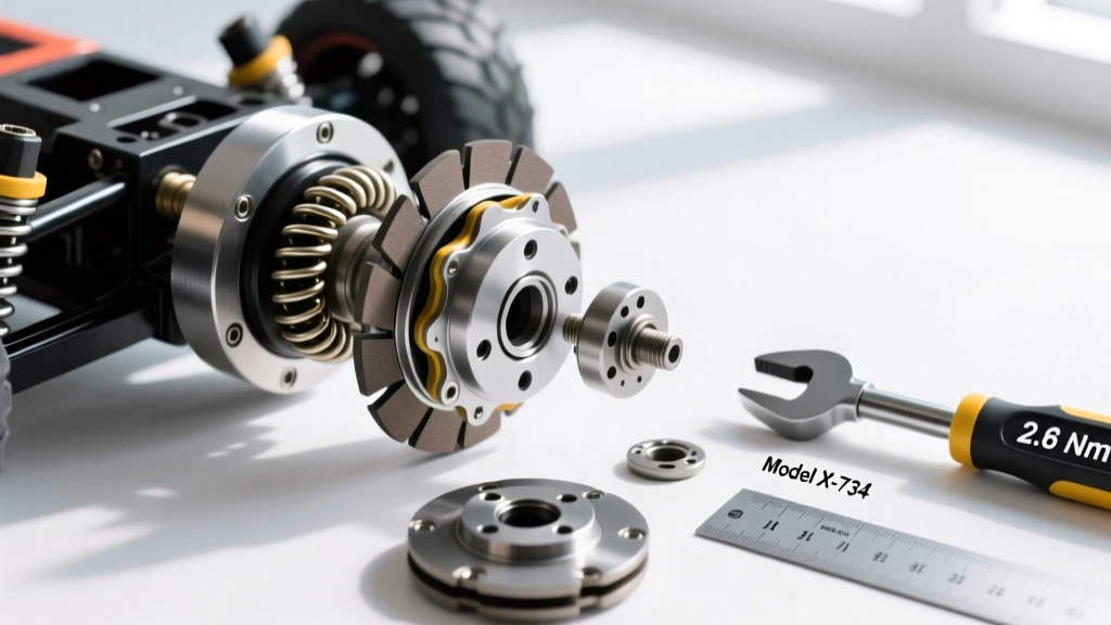
Professional kits, such as the Lisle Corporation 43120 Heavy Duty Fan Clutch Wrench Set, include deep-offset wrenches in 36mm, 47mm, and 58mm sizes, alongside a pulley holding tool. Identify the flat spots on the water pump pulley and insert the holding tool's pins to lock the pulley from rotating.
Step 3: Apply Torque and Shock Loading
Because these nuts are often installed at the factory with high-breakaway torque and secured by years of thermal cycling, static pulling on a breaker bar can snap the water pump shaft. 1. Fit the correct spanner wrench onto the large fan clutch nut. 2. Secure the pulley holder in your non-dominant hand. 3. Instead of steady pressure, use a dead-blow mallet to strike the end of the spanner wrench handle sharply. The kinetic shock breaks the corrosion bond without transferring twisting stress to the delicate water pump bearings.
Step 4: Viscous Chamber Inspection
Once removed, inspect the viscous clutch for silicone fluid leaks around the bimetallic strip or electronic actuator seal. If the internal polydimethylsiloxane fluid has degraded, the clutch will not engage, leading to the thermal heat-soak issues that compromise drivetrain hydraulics.
Diagnostic Data Table: Clutch System Wear Thresholds
Use the following specifications to determine whether components can be reused or must be replaced during your inspection. Data compiled referencing heavy-duty aftermarket standards from South Bend Clutch.
| Component | Measurement / Spec | Failure Threshold | Action Required |
|---|---|---|---|
| Dual Mass Flywheel (DMF) Axial Runout | 0.000" - 0.030" | > 0.050" | Replace DMF Assembly |
| DMF Rotational Freeplay | 5° - 15° tooth-to-tooth | > 20° | Replace DMF (Internal springs failed) |
| HTOB Air Gap | 0.100" - 0.150" | < 0.050" | Adjust master pushrod or add shims |
| Clutch Fork Pad Thickness | Factory Spec (Varies) | > 1/16" groove depth | Replace fork and pivot ball |
| Pressure Plate Diaphragm Finger Wear | Smooth, even contact | > 0.030" groove | Replace Pressure Plate |
| Fan Clutch Nut Torque (Reinstall) | 45 - 65 ft-lbs (Typical) | N/A | Use thread locker if specified by OEM |
Friction Assembly Evaluation: Organic vs. Ceramic vs. Kevlar
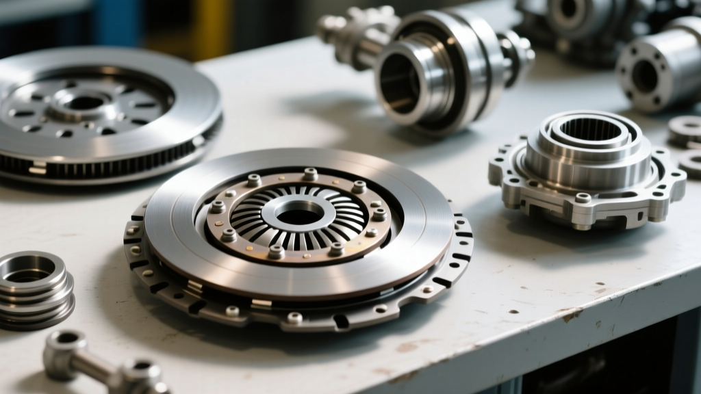
When the flywheel and pressure plate are exposed, evaluate the friction material based on the vehicle's operational profile.
- Organic (Full-Faced): Best for daily driving and towing under 15,000 lbs. Inspect for heat checking (small radial cracks) and marcel spring integrity. If the friction material is worn to within 0.010" of the rivet heads, replacement is mandatory.
- Ceramic (Puck Style): Common in high-horsepower competition setups (800+ hp). Inspect for chunking or shattered pucks. Ceramic requires aggressive pedal effort and generates high chatter; ensure the driveline U-joints and differential backlash have been inspected concurrently, as ceramic clutches transfer severe shock loads.
- Kevlar/Aramid: Offers high tensile strength but requires a specific break-in procedure. If inspecting a used Kevlar clutch, look for glazing. Kevlar glazes easily if slipped excessively at low RPMs. Glazed Kevlar cannot be sanded; it must be professionally bead-blasted or replaced.
2026 Market Pricing and Part References
Budgeting for a comprehensive clutch system overhaul requires accurate forecasting. As of early 2026, supply chain stabilization has normalized pricing for heavy-duty drivetrain components, though raw material costs for advanced friction composites remain elevated.
- OEM Replacement (e.g., LuK / Sachs DMF Kits): $850 - $1,400. Ideal for stock 2010-2024 heavy-duty trucks. Includes DMF, organic disc, pressure plate, and alignment tool.
- Performance Upgrades (e.g., South Bend 3250 / 3600 Series): $1,600 - $2,800. Features Single Mass Flywheel (SMF) conversions with dual-disc organic/ceramic hybrids. Eliminates DMF failure points but increases gear rattle at idle.
- Tooling Investment (Fan Clutch & HTOB Setup): $120 - $250 for professional-grade spanner sets and dial indicators. Essential for any shop performing frequent longitudinal powertrain services.
Final Assembly Protocol
When reinstalling the transmission, always use new flywheel bolts (typically Torque-to-Yield). For example, Cummins flywheel bolts often require a multi-step torque sequence: 35 ft-lbs, followed by 70 ft-lbs, and a final 90-degree turn. Failure to adhere to TTY specifications will result in flywheel warpage under thermal load, instantly negating the meticulous inspection process you just completed.