Introduction: The Drivetrain Treasure Hunt
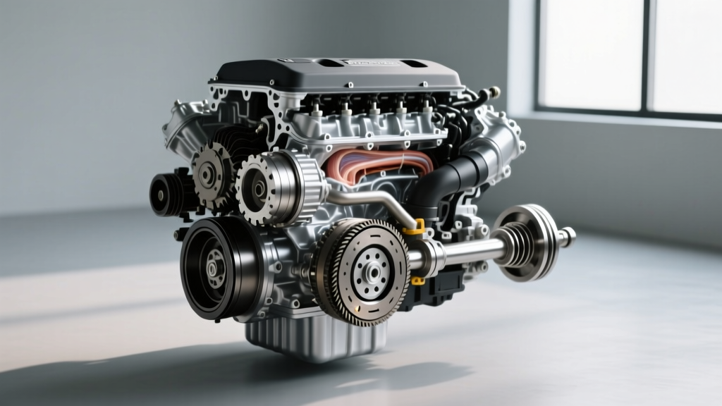
When an apprentice mechanic first asks, 'where is car transmission located?', the answer is never just a simple point under the hood. The physical location of the transmission dictates the entire architecture of the drivetrain, and tracing its housing is the most effective way to master essential transmission terminology. In this step-by-step guide, we will physically trace the power flow from the engine to the wheels, decoding the terminology of modern automatic transmissions along the way.
Step 1: Identify the Drivetrain Layout
Before you can locate the unit, you must identify the vehicle's platform.
Front-Wheel Drive (FWD): The Terminology of the Transaxle
In FWD vehicles (like the Honda Civic or Toyota Camry), the transmission is located transversely beside the engine. Here, the correct terminology is transaxle. A transaxle integrates the transmission gears, the differential, and the final drive into a single casing.
Rear-Wheel Drive (RWD): The Longitudinal Transmission
In RWD platforms (like the Chevrolet Silverado or Ford Mustang), the transmission is mounted longitudinally, directly behind the engine. It is a standalone unit that sends power backward via a driveshaft to a separate rear differential.
All-Wheel Drive (AWD) & 4WD: Transfer Case Integration
AWD and 4WD vehicles feature a transmission mated to a transfer case, which splits torque between the front and rear axles via chain-driven or gear-driven internal mechanisms.
Step 2: Tracing the Power Flow (External Terminology)
Once you are under the vehicle, follow the engine block rearward (or toward the passenger side in FWD). You will encounter these critical external components mapped in the table below.
| Terminology | Definition | Physical Location |
|---|---|---|
| Bell Housing | Conical casing bridging engine and transmission | Front of transmission case |
| Tail Shaft Housing | Rear extension housing the output shaft bearings | Rear of RWD transmission case |
| Dipstick Tube | Guide for checking fluid level (obsolete on many 2026 models) | Side or top of transmission case |
| Shift Linkage | Mechanical cable connecting gear selector to manual valve | Side of transmission case, near bell housing |
| TEHCM / TCM | Transmission Electro-Hydraulic Control Module | External side mount or Internal pan mount |
Step 3: Locating the Torque Converter and Bell Housing
The intersection of the engine and transmission is a hotbed of vital terminology.
- The Bell Housing: This is the conical metal casing that bridges the engine block and the transmission case. It houses the torque converter and protects it from road debris.
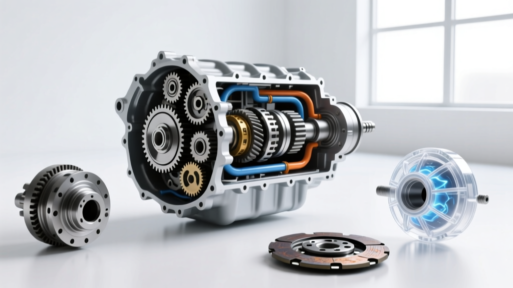
- The Torque Converter: Located entirely inside the bell housing, this fluid coupling replaces the mechanical clutch. It consists of an impeller (pump), a turbine, a stator, and a lock-up clutch.
- Inspection Cover: On many RWD trucks, such as those equipped with the GM 6L80, a small metal or plastic inspection cover at the bottom of the bell housing allows mechanics to view the torque converter flexplate bolts and read TDC (Top Dead Center) timing marks.
Step 4: Decoding the Underbelly (Pan, Valve Body, and Mechatronics)
Looking at the bottom of the transmission case reveals the fluid management systems.
The Transmission Oil Pan
This stamped steel or cast aluminum reservoir holds the automatic transmission fluid (ATF). For example, the ZF 8HP 8-speed automatic uses a specialized plastic pan that integrates the fluid filter. When servicing a ZF 8HP, the pan bolts require a precise torque of 10 Nm (89 lb-in) in a crisscross pattern to prevent warping.
The Valve Body
Located just above the pan, the valve body is the hydraulic control center. It contains a maze of channels and shift valves that direct pressurized ATF to the appropriate clutch packs.
The Mechatronic Unit
In modern transmissions like the ZF 8HP or Ford 10R80, the Transmission Control Module (TCM) and the valve body are merged into a single 'mechatronic' unit submerged in the ATF. Replacing a faulty mechatronic sleeve or complete unit typically costs between $850 and $1,400 for OEM parts alone.
'As we move through 2026, the physical footprint of the traditional automatic transmission is shrinking in favor of integrated e-axles and hybrid drive units. However, the foundational terminology of planetary gearsets and torque conversion remains the bedrock of automotive drivetrain diagnostics.' — SAE International Drivetrain Standards Committee
Step 5: Understanding Internal Gearset Terminology
While you cannot see them without a teardown, understanding where these components sit inside the main case is crucial for diagnostics.
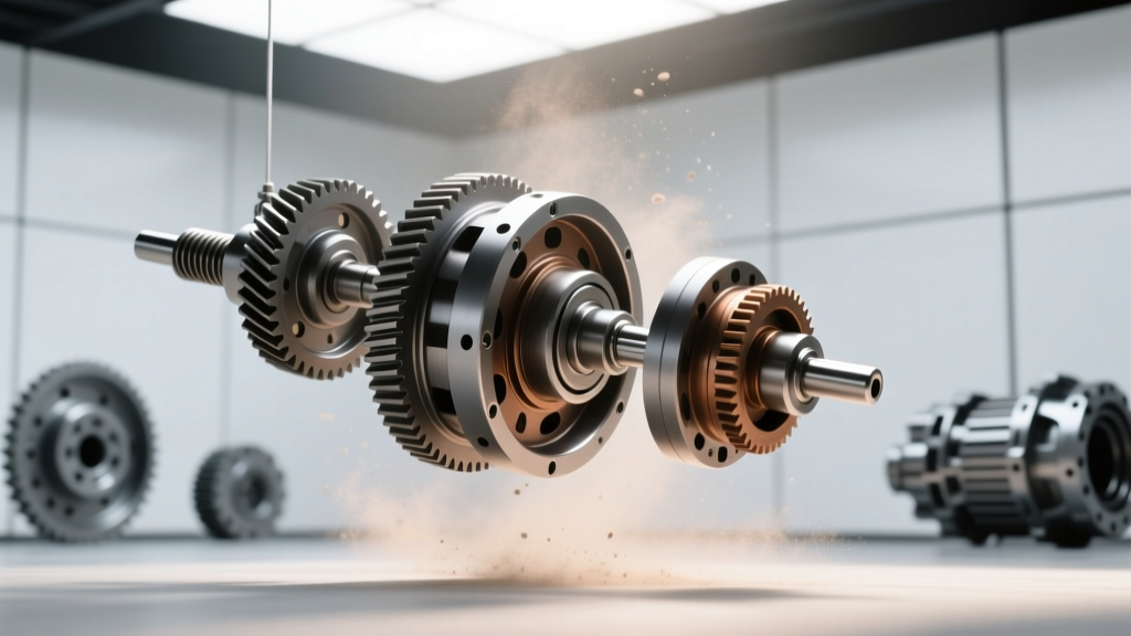
- Planetary Gearsets: The core of automatic shifting. A single gearset comprises a Sun Gear (center), Planet Gears (orbiting), a Planet Carrier (holding the planets), and a Ring Gear (outer teeth).
- Friction Clutches and Bands: These are the braking mechanisms that hold specific parts of the planetary gearset stationary to achieve different gear ratios.
- Accumulators: Hydraulic shock absorbers that cushion the engagement of clutches to ensure smooth shifts.
Step 6: Mapping Sensors, Solenoids, and Cooling Lines
Modern transmissions rely on a network of electronic inputs and hydraulic outputs.
- Speed Sensors: Locate the Input Shaft Speed (ISS) and Output Shaft Speed (OSS) sensors. The ISS is typically buried near the bell housing, reading the torque converter hub, while the OSS is located near the tail shaft housing.
- Transmission Fluid Temperature (TFT) Sensor: Usually integrated into the valve body. The TCM uses this data to adjust line pressure; cold ATF requires higher pressure to prevent clutch slip.
- Cooler Lines: Trace the two metal or rubber lines exiting the transmission case. These route hot ATF to the transmission cooler. A pinhole leak here can result in a loss of 1-2 quarts of fluid, leading to immediate clutch pack burnout.
Real-World Application: GM 6L80 vs. ZF 8HP
To solidify your terminology, let us compare two industry-standard transmissions referenced by General Motors Powertrain Engineering and global OEMs.
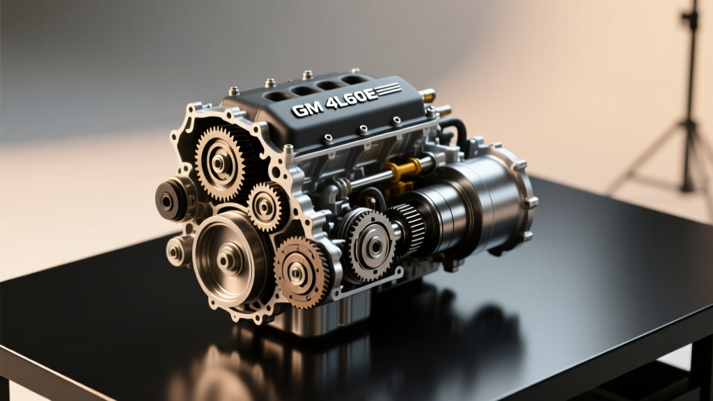
- GM 6L80 (6-Speed RWD): Total dry fill capacity is roughly 10.5 quarts. Features a standalone TEHCM mounted externally on the side of the case, making electronic diagnostics easier without dropping the pan. Pan bolt torque spec: 10 Nm (89 lb-in).
- ZF 8HP (8-Speed RWD/AWD): Total dry fill capacity is 9.2 liters. Features an internal mechatronic unit. The absence of an external dipstick means fluid level checks must be performed via the overflow plug at the bottom of the pan while the fluid is between 30°C and 50°C.
Summary Checklist for Drivetrain Identification
Knowing where the car transmission is located is only the beginning. By physically mapping the bell housing, the oil pan, and the output shaft, you transform abstract terminology into tangible, wrench-turning knowledge. Next time you slide under a vehicle, trace the power flow, identify the layout, and apply the precise terminology required for professional-grade diagnostics.