The Architecture of the 4L80E Output Speed Sensor
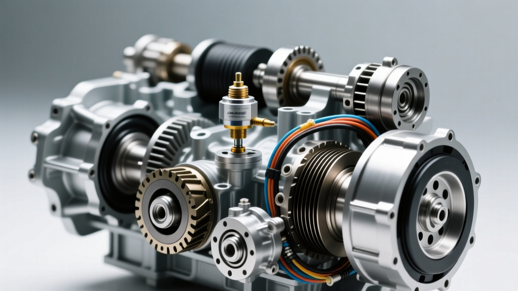
The GM Turbo-Hydramatic 4L80E is legendary for its heavy-duty durability, finding its way into everything from C/K 2500/3500 trucks to high-end luxury vehicles like Bentley and Jaguar. At the heart of its electronic control strategy is the output speed sensor (OSS). Unlike modern 8-speed or 10-speed transmissions that rely on complex 3-wire Hall-effect sensors, the output speed sensor 4l80e transmission models utilize is a 2-wire Variable Reluctance (VR) magnetic pickup.
The PCM (Powertrain Control Module) or TCM relies on the OSS signal to calculate vehicle speed, govern shift mapping, and dictate Torque Converter Clutch (TCC) lockup. More importantly, the PCM compares the OSS data against the Input Speed Sensor (ISS) to calculate the gear ratio in real-time. If the calculated ratio deviates from the commanded gear, the PCM will trigger a Diagnostic Trouble Code (DTC) and often command limp mode, locking the transmission in second or third gear to protect the clutch packs.
Variable Reluctance Physics and Signal Generation
Because the 4L80E OSS is a VR sensor, it does not receive a 5V or 12V reference signal from the PCM. Instead, it acts as a miniature alternating current (AC) generator. The sensor contains a permanent magnet wrapped in a coil of fine copper wire. As the output shaft rotates, a 40-tooth ferrous reluctor ring passes through the sensor's magnetic field. This changing magnetic flux induces an AC voltage sine wave that travels back to the PCM.
The PCM measures two distinct characteristics of this sine wave:
- Frequency: Determines the rotational speed (RPM) of the output shaft.
- Amplitude: The voltage height, which naturally increases as shaft speed increases. At idle in gear, the signal may only be 0.5V AC, but at 70 MPH, it can exceed 3.0V AC.
OEM Diagnostic Specifications & Parameters
When testing the circuit, technicians must adhere to strict OEM baselines. Deviations in resistance usually indicate internal coil degradation or fluid contamination inside the sensor casing.
| Parameter | Specification / Baseline |
|---|---|
| Sensor Architecture | Variable Reluctance (2-Wire Magnetic Pickup) |
| Internal Resistance (at 68°F / 20°C) | 1,500 - 2,500 Ohms |
| AC Voltage Output (Idle, in Gear) | 0.4V - 1.2V AC |
| AC Voltage Output (Highway Speed) | 2.0V - 4.5V AC |
| Reluctor Ring Profile | 40 Teeth (Pressed onto Output Shaft) |
| PCM DTC Triggers | P0722, P0723, P0502 |
| Hold-Down Bolt Torque | 11 lb-ft (15 Nm) |
Advanced Waveform Analysis with Oscilloscopes
In 2026, relying solely on a multimeter is insufficient for intermittent transmission faults. While a multimeter can verify static resistance, it cannot capture micro-second signal dropouts caused by a chipped reluctor tooth or electromagnetic interference (EMI). Using a digital storage oscilloscope (DSO) like a PicoScope is the industry standard for VR sensor diagnosis.
Reading the Sine Wave
Connect your scope leads to the OSS signal and low-reference circuits at the transmission pass-through connector. Spin the rear driveshaft by hand (with the vehicle safely on a lift and in neutral). A healthy 4L80E OSS will display a uniform, symmetrical AC sine wave. The peaks and valleys should be consistent in amplitude. If you notice a sudden "flat spot" or missing wave cycle every 40 teeth, the reluctor ring on the output shaft is damaged, or metallic debris is stuck to the sensor's magnetic tip, distorting the air gap.
The Hidden Failure Mode: Internal Harness Chafing
If your scan tool flags an erratic speed sensor, 4l80e transmission faults often trace back to the internal wiring harness rather than the sensor itself. This is a notorious edge case that traps novice mechanics into replacing perfectly good sensors.
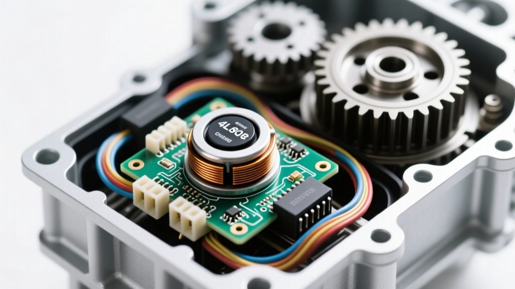
The 4L80E internal wiring harness routes from the pass-through connector, down past the valve body, and wraps around the transmission pan to reach the OSS and ISS. Over time, vibration and fluid turbulence cause the harness to rub against the sharp aluminum edges of the transmission case or the metal transmission filter. The insulation wears through, allowing the OSS AC signal to short to ground or cross-talk with the 12V solenoid circuits.
Pro-Tip: If you have a P0722 (Output Speed Sensor No Signal) and the sensor tests perfectly on the bench, drop the pan and physically trace the internal harness. Look for shiny, worn spots on the wiring loom. If found, the entire internal harness must be replaced to prevent PCM driver damage.
Step-by-Step Replacement and Torque Protocols
Replacing the OSS requires dropping the transmission pan, as the sensor is located inside the case, near the rear output shaft. Expect to lose approximately 6 to 8 quarts of Dexron VI fluid during this service.
- Fluid Drain & Pan Removal: Loosen the 18 pan bolts gradually. Allow the Dexron VI to drain into a calibrated catch pan to check for excessive clutch material or metallic shavings.
- Sensor Extraction: Locate the OSS near the rear of the valve body. Remove the single 10mm hold-down bolt. Gently twist the sensor back and forth to break the O-ring seal. Never pry with a screwdriver, as scoring the aluminum case will cause a permanent fluid leak.
- O-Ring Lubrication: Lubricate the new sensor's O-ring with fresh Dexron VI. Installing it dry will cause the O-ring to pinch and fail within 500 miles.
- Torque Specification: Reinstall the 10mm bolt and torque to exactly 11 lb-ft (15 Nm). Over-torquing can crack the sensor's plastic housing or strip the soft aluminum case threads.
- Harness Routing: Secure the internal wiring harness away from the filter and case edges using high-temperature zip ties or OEM retaining clips before reinstalling the pan.
Sourcing Economics: OEM vs. Aftermarket
When sourcing replacement components, the transmission electronics market is flooded with cheap, out-of-spec imports. For the 4L80E, the VR sensor's internal coil winding quality dictates its lifespan and signal clarity. We strongly recommend sticking to OEM or premium-tier aftermarket manufacturers.
- ACDelco (OEM): Part number 213-1676 (or VIN-specific equivalent). Priced between $35 and $55. This is the exact unit installed on the GM assembly line and guarantees the correct 1,500-2,500 ohm resistance curve.
- Standard Motor Products (SMP): Part number SC103. Priced around $30. SMP is a highly respected Tier 1 supplier and offers excellent quality control for VR sensors.
- Budget Imports: Often found for $12-$18. These frequently suffer from poor internal potting, leading to fluid intrusion and premature coil shorts. Avoid these for commercial or heavy-duty fleet applications.
For comprehensive diagnostic flowcharts and wiring diagrams, technicians frequently reference the OBD-Codes P0722 Troubleshooting Guide and cross-reference pinouts with ACDelco OEM Sensor Specifications. Proper diagnosis saves time, prevents unnecessary PCM replacements, and keeps these legendary heavy-duty transmissions shifting flawlessly on the road.