The Evolution of the Tractor Clutch: From Mechanical to Hydraulic
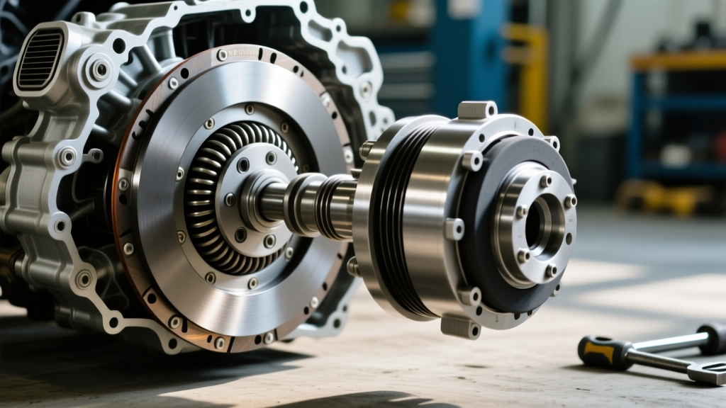
In modern agriculture and heavy-duty landscaping, the mechanical dry clutch has been largely relegated to compact utility machines. As of 2026, the vast majority of mid-to-large horsepower tractors—such as the John Deere 8R series, Case IH Magnum CVX, and New Holland T7 Auto Command—utilize hydraulically actuated wet clutch packs. These systems rely on precise hydraulic pressure to engage sintered bronze or carbon-fiber friction discs running in a continuous oil bath. While this design offers infinite modulation and eliminates mechanical linkage wear, it introduces complex hydraulic failure modes that can lead to catastrophic transmission damage if ignored.
This preventive maintenance guide focuses on hydraulic tractor clutch diagnosis, equipping technicians and fleet managers with the exact specifications, pressure testing protocols, and fluid analysis techniques required to prevent premature clutch pack failure.
System Architecture: Shared Sump vs. Isolated Hydraulics
Before diagnosing a hydraulic clutch issue, it is critical to identify the fluid delivery architecture of the specific tractor model. Agricultural transmissions generally fall into two categories:
- Shared Sump Systems (Heavy Ag): Transmissions like the John Deere PowrQuad or Case IH Full Powershift share a single fluid reservoir (often 15 to 25 gallons) between the hydraulic implement pumps, the transmission charge pump, and the wet clutch packs. Contamination from a failing implement pump can directly destroy clutch friction material.
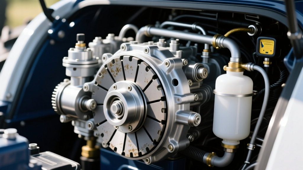
- Isolated Systems (Compact/Utility): Smaller tractors, such as the Kubota M7 series or BX hydrostatic models, often use an isolated master/slave cylinder setup actuated by DOT 3 or DOT 4 brake fluid, completely separate from the Universal Tractor Fluid (UTF) in the rear axle.
Fluid Specifications and Preventive Replacement Intervals
Using the incorrect fluid is the leading cause of wet clutch slippage and squawk (harsh engagement). Friction modifiers in UTF are specifically engineered for the paper or sintered bronze materials used in tractor clutch packs.
| Tractor Class / Transmission | Required Fluid Spec | Capacity (Approx.) | Service Interval | Est. Fluid Cost (2026) |
|---|---|---|---|---|
| John Deere PowrQuad / PowrReverser | Hy-Gard (J20C / J20D) | 12 - 18 Gal | 1,200 Hours | $18 - $24 / Gal |
| Case IH CVX / Magnum Powershift | Hy-Tran Plus (MS-1207) | 15 - 22 Gal | 1,200 Hours | $20 - $28 / Gal |
| Kubota BX / B-Series (Isolated Clutch) | DOT 4 Brake Fluid | 0.5 - 1 Qt | 24 Months | $8 - $12 / Qt |
Reference: Always cross-reference with the SAE J20C Off-Road Fluid Standards to ensure aftermarket fluids meet the exact frictional requirements of the OEM wet clutch packs.
Diagnostic Matrix: Symptoms vs. Hydraulic Faults
When a tractor operator reports clutch slipping, harsh shifting, or a spongy pedal, the root cause is rarely the clutch pack itself until hydraulic integrity has been verified. Use the following diagnostic matrix to isolate the hydraulic fault.
| Reported Symptom | Primary Hydraulic Suspect | Diagnostic Action Required |
|---|---|---|
| Spongy or 'Mushy' Clutch Pedal (Isolated System) | Aerated DOT fluid, degraded master cylinder cup seals | Vacuum bleed system; inspect master cylinder pushrod travel. |
| Harsh Engagement / Driveline 'Clunk' | Failed accumulator nitrogen charge, stuck PWM solenoid | Test accumulator pre-charge pressure; scan for solenoid PWM duty cycle faults. |
| Clutch Slipping Under Heavy Draft Load | Low charge pump pressure, clogged suction screen, worn piston seals | Install 600 PSI gauge at clutch feed port; verify minimum 220 PSI apply pressure. |
| Delayed Engagement (PTO or Range Shift) | Spool valve stiction, varnished fluid from overheating | Sample fluid for oxidation; drop valve body and inspect spool lands for scoring. |
Advanced Pressure Testing Protocols
Visual inspections are insufficient for diagnosing modern tractor clutch hydraulics. You must quantify the hydraulic apply pressure. According to Agriculture.com machinery maintenance guidelines, verifying charge and clutch pressures is the only definitive way to rule out internal transmission leaks before splitting the tractor chassis.
Step-by-Step Clutch Feed Pressure Test
- Locate the Test Port: On most John Deere and Case IH powershift transmissions, the clutch feed pressure test ports are located on the side of the transmission housing or directly on the valve body. They typically utilize a 1/8-inch or 1/4-inch JIC 37-degree flare or ORFS (O-Ring Face Seal) fitting.
- Connect the Gauge: Use a liquid-filled 0-600 PSI hydraulic test gauge to dampen pressure spikes. Connect using a high-pressure PTFE-lined hose rated for at least 1,000 PSI working pressure.
- Establish Baseline Charge Pressure: Start the tractor and run at idle (typically 850-900 RPM). Main charge pump pressure should read between 180 PSI and 240 PSI. If pressure is below 160 PSI at idle, the clutch packs will slip under load. This indicates a failing charge pump, a clogged transmission suction screen, or a blown charge pump O-ring.
- Verify Modulated Apply Pressure: Engage the PTO or shift into a forward range. The PWM (Pulse Width Modulation) solenoid should ramp pressure up to 220 PSI - 300 PSI (depending on the specific clutch pack). A failure to reach peak pressure within 0.8 seconds indicates a leaking internal clutch piston seal or a failing solenoid.
The Role of PWM Solenoids and Accumulators
In 2026, virtually all high-horsepower agricultural CVT and powershift transmissions utilize PWM solenoids to control clutch engagement. Unlike simple on/off solenoids, PWM solenoids pulse rapidly (often 50-100 Hz) to modulate fluid volume, allowing the transmission control module (TCM) to 'feather' the clutch pack for seamless shifts.
Diagnostic Tip: If a specific range clutch is slipping, swap the suspected PWM solenoid with a known-good solenoid from another clutch circuit on the same valve body. If the fault moves with the solenoid, replace the unit. OEM replacement solenoids typically cost between $140 and $280. Ensure you torque the solenoid retaining bolts to the exact OEM specification (usually 10-12 Nm) to prevent valve body warping.
Furthermore, the hydraulic accumulator acts as a shock absorber. It contains a nitrogen-charged bladder that absorbs the hydraulic spike when a clutch pack fully engages. If the nitrogen bleeds out over time, the operator will experience harsh, jarring shifts that can crack cast transmission housings or shear input shaft splines. Accumulators cannot be serviced; they must be replaced (Cost: $350 - $600).
Edge Case: Cavitation and Aeration in Shared Sumps
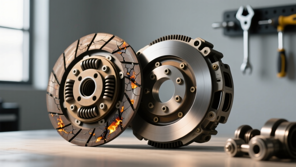
A common edge case in heavy ag tractors operating on steep inclines is hydraulic pump cavitation. If the fluid level drops below the suction pickup, or if the breather cap becomes clogged with dust and debris, the charge pump will ingest air. Aerated UTF fluid is compressible. When this aerated fluid reaches the clutch actuator, the clutch pack will not fully clamp, resulting in immediate glazing of the friction discs. Always check the transmission breather cap during routine 500-hour service intervals to ensure the sump can breathe.
Preventive Maintenance Checklist for Fleet Managers
To maximize the lifespan of a tractor clutch system—which can cost upwards of $4,000 to $8,000 to replace when factoring in chassis-splitting labor—implement the following preventive maintenance schedule:
- Every 250 Hours: Inspect isolated master/slave cylinder lines for micro-leaks. Check fluid level in the clutch reservoir.
- Every 500 Hours: Clean the external transmission breather cap. Inspect external hydraulic line O-rings and banjo bolt washers.
- Every 1,000 Hours: Drop the transmission suction screen (if equipped) and clean with solvent and compressed air. Inspect for excessive brass or steel particulate, which indicates early clutch pack or thrust bearing wear.
- Every 1,200 - 1,500 Hours: Perform a complete UTF fluid and filter change. Take a fluid sample for spectrographic analysis to monitor friction material degradation. For more on fluid analysis, consult resources from Machinery Lubrication.
Conclusion
Diagnosing a hydraulic tractor clutch requires moving beyond simple pedal-feel assessments and embracing fluid dynamics, pressure testing, and electronic solenoid diagnostics. By strictly adhering to OEM fluid specifications, monitoring charge pump pressures, and maintaining pristine suction screens, technicians can prevent the vast majority of catastrophic wet clutch failures. In modern heavy machinery, the hydraulic system is the lifeblood of the drivetrain; treat its maintenance with the precision it demands.