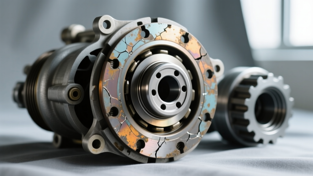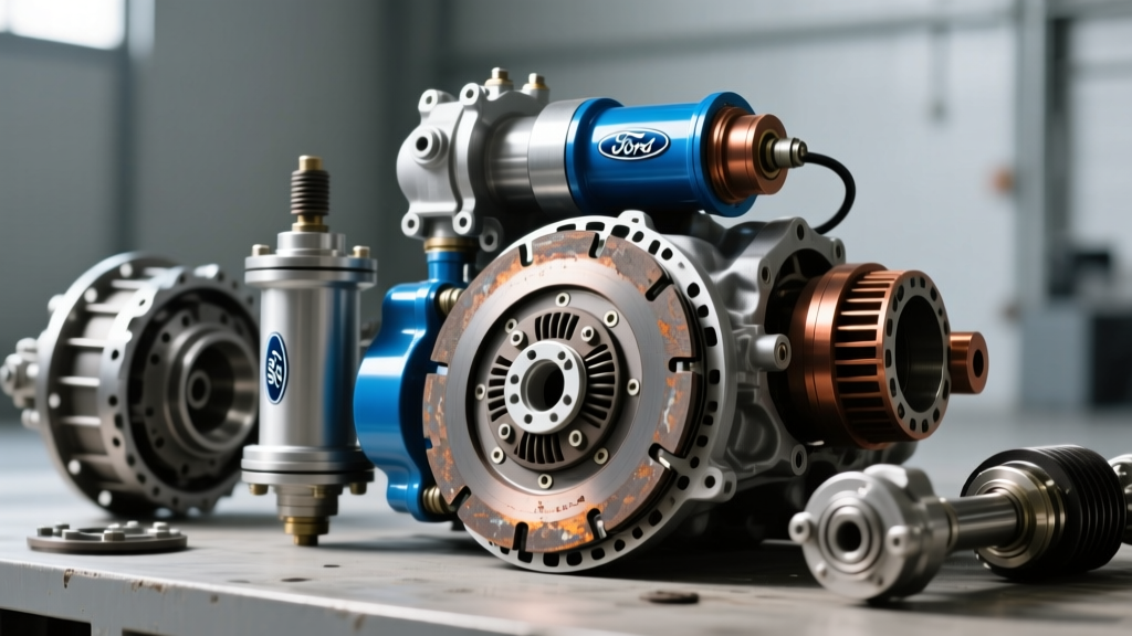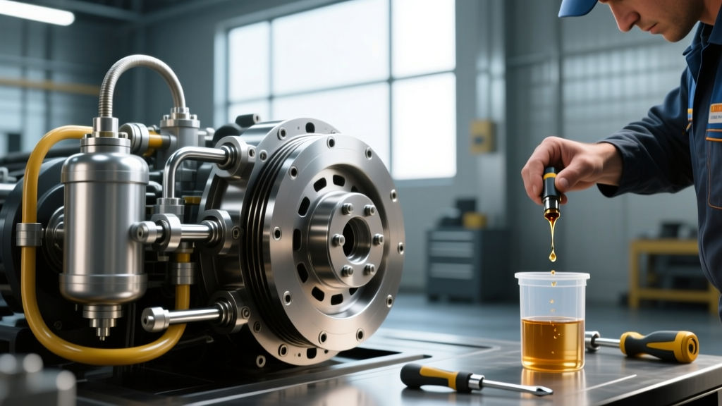
As the commercial transportation industry moves deeper into 2026, the prevalence of automated manual transmissions (AMTs) like the Eaton Endurant and ZF TraXon has reshaped the heavy-duty landscape. However, traditional manual transmissions and hybrid hydraulic actuation systems remain foundational in vocational trucks, severe-duty applications, and legacy fleets. When it comes to heavy-duty truck clutches, the hydraulic actuation system is the critical link between driver input and mechanical disengagement. A failure in this closed-loop hydraulic circuit doesn't just cause drivability issues; it leads to catastrophic clutch pack degradation and expensive roadside downtime.
This preventive maintenance guide provides a deep-dive diagnostic framework for hydraulic clutch systems in Class 7 and Class 8 trucks. We will cover fluid degradation metrics, precise stroke measurements, and advanced bleeding protocols to ensure maximum component lifespan.
The Anatomy of Class 8 Hydraulic Clutch Actuation
Unlike passenger vehicles, heavy-duty truck clutches utilize high-volume hydraulic circuits designed to overcome the immense clamping force of multi-plate or large-diameter diaphragm spring assemblies (often exceeding 2,800 lbs of clamp load). The system typically consists of three primary nodes:
- The Master Cylinder: Usually mounted on the firewall or under the cab, converting mechanical pedal force into hydraulic pressure. Common OEM replacements include the Eaton K-3533 or equivalent Williams Controls units.
- The Hydraulic Line Assembly: Modern fleets have largely transitioned from traditional rubber hoses to PTFE (Teflon) lined, stainless-steel braided hoses to prevent volumetric expansion under high thermal loads.
- The Slave Cylinder: Heavy-duty trucks predominantly use Concentric Slave Cylinders (CSC) mounted directly on the transmission input shaft bearing retainer, or external actuation arms paired with ZF ConAct pneumatic-hydraulic assist modules.
Preventive Maintenance: Fluid Degradation and Moisture Ingress
The most common point of failure in hydraulic truck clutches is not mechanical wear, but fluid degradation. Most heavy-duty systems utilize DOT 4 or specialized low-viscosity DOT 4+ fluids. Because glycol-based brake and clutch fluids are hygroscopic, they absorb ambient moisture through microscopic pores in older rubber lines and reservoir breathers.
As moisture content increases, the fluid's wet boiling point drops drastically. In vocational trucks operating in high-ambient-temperature environments (e.g., oilfield or heavy-haul applications), localized heat from the transmission bell housing can cause moisture-laden fluid to vaporize, resulting in a spongy pedal and failure to disengage.
Fluid Specification and Service Interval Matrix
| Fluid Type | Dry Boiling Point | Wet Boiling Point (3.7% H2O) | Preventive Replacement Interval |
|---|---|---|---|
| Standard DOT 4 | 446°F (230°C) | 311°F (155°C) | Every 24 months / 200,000 miles |
| DOT 4+ (Low Viscosity) | 473°F (245°C) | 338°F (170°C) | Every 36 months / 300,000 miles |
| DOT 5.1 (Glycol-Based) | 518°F (270°C) | 374°F (190°C) | Every 48 months / 400,000 miles |
| Mineral Oil (LHM+) | N/A (Non-Hygroscopic) | N/A | Every 60 months (Euro-spec only) |
Note: Never mix DOT 5 (Silicone-based) with DOT 4 or DOT 5.1. Silicone fluid will destroy the EPDM seals used in standard heavy-duty master and slave cylinders, leading to immediate bypass leaks.
Diagnostic Framework: Measuring Pedal Free-Play and Stroke
Before replacing a suspected failing clutch friction disc, a thorough hydraulic diagnosis must be performed. The most frequent misdiagnosis of a 'slipping clutch' is actually a hydraulically induced preload issue.
1. Master Cylinder Pushrod Clearance
There must be a precise air gap between the clutch pedal pushrod and the master cylinder piston. For most Freightliner and Peterbilt applications, this clearance should be between 0.010" and 0.020". If the pushrod is adjusted too tightly (zero clearance), the master cylinder piston will not fully retract. This blocks the internal bypass port, preventing fluid from returning to the reservoir. As the fluid heats up and expands, it applies continuous, unintended pressure to the clutch release bearing, causing the clutch to slip and prematurely destroying the diaphragm spring.
2. Slave Cylinder Stroke Verification
Using a dial indicator or precision calipers, measure the slave cylinder stroke during a full pedal depression. For a standard 15.5-inch heavy-duty truck clutch, the required hydraulic stroke at the release fork or CSC is typically 0.500" to 0.625". If the measured stroke is less than 0.450", the system is suffering from volumetric loss (air ingress, internal master cylinder bypassing, or swollen hydraulic lines), and the clutch will drag or fail to disengage during shifts.
Bleeding Protocols: Avoiding Seal Damage and Micro-Bubbles
Bleeding the hydraulic circuit on a Class 8 truck requires strict adherence to pressure limits. The internal seals of a Concentric Slave Cylinder are delicate; excessive pressure will invert or extrude the lip seals, necessitating a transmission drop to replace a $600 CSC assembly.
"When pressure bleeding a heavy-duty hydraulic clutch system, never exceed 25 to 30 PSI at the master cylinder reservoir. High-pressure shop bleeders set to 50+ PSI will blow out the internal slave cylinder check valves and ruin the hydraulic line quick-connect fittings." — Fleet Maintenance Best Practices, TMC Recommended Practice
Step-by-Step Reverse Bleeding Procedure
For stubborn air pockets trapped in the upward-routed hydraulic lines of cab-over-engine (COE) trucks, reverse bleeding is the most effective method.
- Connect a reverse bleeder to the slave cylinder bleeder screw. Ensure the bleeder screw is torqued to 8-10 Nm (71-89 lb-in) to prevent stripping the soft brass threads.
- Slowly inject DOT 4+ fluid upward, pushing air naturally toward the highest point (the master cylinder reservoir).
- Monitor the reservoir to prevent overflow. Use a fluid extraction syringe to remove excess fluid, maintaining the level 1/4 inch below the MAX line.
- Cycle the clutch pedal 20 times slowly to seat the internal seals, then re-verify pedal free-play.
Troubleshooting Matrix: Symptoms to Hydraulic Faults
Use the following diagnostic matrix to map driver complaints to specific hydraulic faults before authorizing a transmission removal.
- Symptom: Pedal sinks to the floor when held at a stoplight.
Diagnosis: Internal master cylinder seal bypass. Fluid is leaking past the primary cup seal back into the reservoir. Replace master cylinder (Approx. cost: $180-$350 for part). - Symptom: Clutch drags or grinds going into gear, but pedal feels firm.
Diagnosis: Volumetric expansion due to degraded rubber hydraulic hose, or a seized external release fork pivot ball. Check hose for 'ballooning' under pressure. - Symptom: Clutch slips under heavy load, pedal has no free-play.
Diagnosis: Blocked master cylinder bypass port due to incorrect pushrod adjustment or swollen pedal bumper stop. Adjust pushrod to restore 0.015" clearance. - Symptom: Spongy pedal that pumps up firm after 3 strokes.
Diagnosis: Air ingress at the quick-connect fittings or a micro-fracture in the master cylinder reservoir cap diaphragm. Replace cap and O-rings, perform vacuum bleed.
Conclusion: The ROI of Hydraulic Preventive Maintenance
Ignoring the hydraulic circuit is a fast track to premature clutch failure. Replacing a heavy-duty clutch pack and CSC requires dropping the transmission, a job that averages 8 to 12 hours of shop labor, pushing total repair costs well past $3,500. By implementing strict fluid flush intervals, verifying pushrod clearances during every PM service, and utilizing low-pressure reverse bleeding techniques, fleets can easily extend the life of their truck clutches to the 750,000-mile mark. For further technical specifications on actuation systems, consult the engineering documentation provided by the Eaton Vehicle Group and ZF Commercial Vehicle Solutions.