Introduction to HVAC Clutch Diagnostics
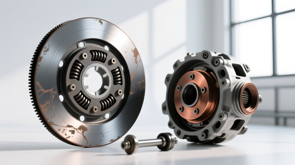
When automotive technicians and enthusiasts discuss clutch systems, the focus typically drifts toward manual transmission friction discs or torque converter lock-up mechanisms. However, the accessory drive system houses a critical electromagnetic friction device that operates under extreme thermal and mechanical stress: the AC compressor clutch. Unlike a transmission clutch that engages and disengages with driver input, the pulley of an automotive AC compressor spins continuously whenever the engine is running. This constant rotation places the entire burden of rotational support on a single, heavily loaded component: the air conditioning compressor clutch bearing. When this bearing begins to fail, it introduces a cascade of secondary symptoms ranging from parasitic drag to catastrophic serpentine belt failure.
Diagnosing a failing AC clutch pulley bearing requires a systematic approach to isolate the fault from adjacent components like the idler pulley, tensioner assembly, or the compressor's internal swashplate. This step-by-step how-to guide will walk you through professional-grade diagnostic procedures—evaluating noise, vibration, and electrical engagement—to accurately pinpoint bearing degradation before it strands you on the highway.
The Anatomy of the AC Compressor Clutch Assembly
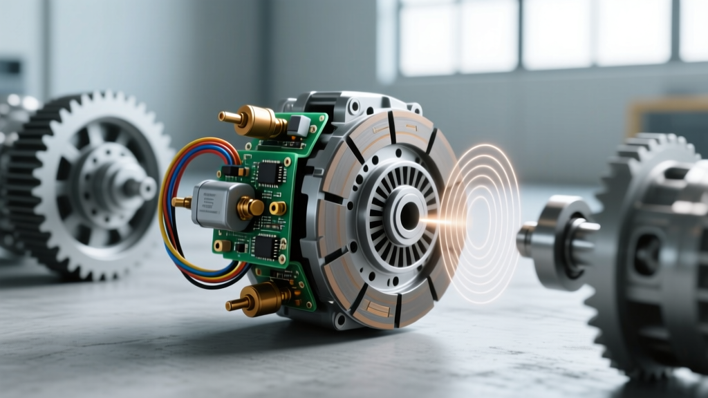
Before diving into diagnostics, it is vital to understand the mechanical triad that makes up the clutch assembly. According to Hella Tech World's HVAC guidelines, the assembly consists of three primary components:
- The Pulley and Bearing Assembly: Driven by the serpentine belt, this component houses a sealed, double-row angular contact ball bearing. It spins freely on the compressor's front snout when the AC is turned off.
- The Electromagnetic Coil: Mounted stationary behind the pulley, this coil generates a magnetic field when energized by the vehicle's climate control module.
- The Friction Plate (Hub/Armature): Splined or keyed to the compressor's main shaft. When the coil energizes, the friction plate is pulled against the spinning pulley face, locking the shaft to the pulley and engaging the compressor.
Because the pulley and its internal bearing rotate 100% of the time the engine is running, the bearing is subjected to continuous radial loads from belt tension, as well as axial thrust loads when the magnetic coil pulls the friction plate inward.
Step 1: Auditory Triage (Isolating the Noise)
The most common early indicator of a failing air conditioning compressor clutch bearing is an auditory anomaly. However, the accessory drive belt transmits sound from all pulleys, making isolation critical. You must differentiate between a slipping belt, a failing tensioner, and the clutch bearing itself.
The Stethoscope Isolation Test
Do not use a standard screwdriver to probe the accessory drive while the engine is running; the risk of catching a tool in the belt and causing severe hand injury is exceptionally high. Instead, use an automotive mechanical stethoscope with a long probe, or a specialized pulley listening tool.
- Start the engine and ensure the climate control is turned OFF. This disengages the friction plate, meaning the compressor shaft is stationary while the pulley spins freely on the bearing.
- Place the stethoscope probe on the stationary front snout of the compressor housing, directly behind the pulley, or on the mounting bracket adjacent to the bearing race.
- Listen for specific frequencies: A high-pitched, metallic squeal that modulates with engine RPM often indicates bearing cage failure or dried-out grease. A low-frequency grinding or growling noise suggests spalling or brinelling on the bearing's inner or outer race.
- Turn the climate control ON. If the noise changes pitch, becomes louder, or turns into a harsh metallic clatter, the issue may be the friction plate rubbing against a warped pulley face, or internal compressor failure, rather than just the pulley bearing.
Step 2: Tactile and Visual Diagnosis (Vibration and Wobble)
Bearing wear inevitably leads to increased internal clearance, manifesting as axial or radial runout. This wobble can cause the serpentine belt to track improperly, leading to premature belt wear and tensioner fatigue.
Visual Runout Inspection
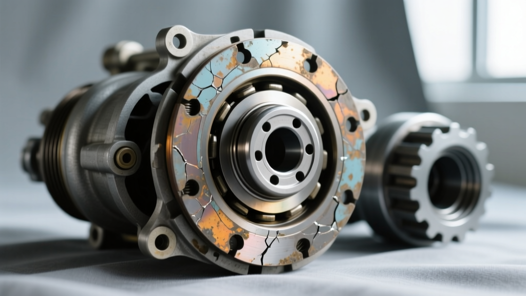
With the engine off and the keys removed from the ignition, visually inspect the pulley gap. Use a bright LED inspection light to look for rust streaks emanating from the center hub of the pulley. This 'bleeding' is a telltale sign that the bearing's internal seals have failed, allowing moisture to enter and grease to escape. Next, grip the top and bottom of the pulley and attempt to rock it in and out (axial play). While a minuscule amount of preload deflection is normal in angular contact bearings, any distinct 'clunk' or visible wobble indicates severe cage degradation.
Dial Indicator Measurement
For definitive proof of runout, mount a magnetic base dial indicator to the engine block. Position the indicator tip against the outer lip of the clutch pulley. Rotate the pulley by hand through one full revolution. According to industry standards outlined by AA1Car's AC Compressor diagnostic library, lateral runout exceeding 0.020 inches (0.50mm) typically warrants immediate bearing replacement, as it will eventually cause the friction plate to drag against the pulley face even when the AC is disengaged.
Step 3: Electrical Coil and Air Gap Verification
Sometimes, what feels like a mechanical bearing bind is actually an electrical failure causing the clutch to partially engage, creating massive friction and heat that transfers into the bearing. You must rule out electrical faults and improper air gaps.
Measuring the Air Gap
The air gap is the distance between the friction plate and the pulley face when disengaged. If the gap is too wide, the coil cannot fully pull the plate in, causing it to slip, glaze, and generate immense heat that cooks the bearing grease. If the gap is too tight, the plate will drag on the pulley when the AC is off, destroying the bearing via continuous friction.
- Target Specification: Most OEM manufacturers (including Denso, Sanden, and GM/Delphi) specify an air gap between 0.40mm and 0.60mm (0.015 to 0.024 inches).
- Tool Required: Use a flat blade feeler gauge. Insert it between the friction plate and the pulley face at three equidistant points around the circumference.
- Correction: If the gap is out of spec, remove the center hub bolt and add or subtract shims located on the compressor shaft behind the friction plate.
Electromagnetic Coil Resistance Test
Disconnect the electrical connector leading to the compressor coil. Set your digital multimeter to the Ohms (Ω) setting. Probe the two terminals on the compressor-side connector. A healthy coil typically reads between 3.0 and 5.0 ohms at 20°C (68°F). A reading of infinite resistance (OL) indicates an open circuit (burned-out coil), while a reading near 0.0 ohms indicates a short. A failing coil can cause erratic engagement, mimicking the shuddering feel of a bad bearing.
Symptom-to-Failure Diagnostic Matrix
Use the following table to cross-reference your physical findings with the most likely internal failure points.
| Observed Symptom | Test Condition | Probable Root Cause | Corrective Action |
|---|---|---|---|
| High-pitched metallic squeal | AC OFF, Engine Running | Bearing grease depletion / cage wear | Replace pulley bearing assembly |
| Low growling / grinding | AC OFF, Engine Running | Race spalling / brinelling | Replace pulley bearing assembly |
| Harsh clatter / vibration | AC ON, Compressor Engaged | Excessive air gap / slipping friction plate | Adjust shims to 0.4mm - 0.6mm |
| Pulley wobble / belt chirp | Engine Running (Any state) | Bearing internal clearance failure | Replace bearing, check snout wear |
| Smoke / burning smell | AC ON, Low Refrigerant Charge | Friction plate slipping, heat transfer | Recharge system, check coil ohms |
Step 4: Teardown, Bearing Specs, and Torque Values
Once you have confirmed the air conditioning compressor clutch bearing is the culprit, the replacement procedure requires specific tooling and adherence to torque specifications to avoid destroying the new components.
Bearing Cross-Reference and Sizing
AC compressor bearings are not universal; they are specific to the compressor family. You must verify the dimensions (Inner Diameter x Outer Diameter x Width). Common OEM configurations include:
- Sanden SD7V16 / SD7B10 (Common in VW/Audi, Mazda): Typically uses a 35x52x20mm double-row angular contact bearing (e.g., NSK 35BD5220T12).
- Denso 10S17C / 10PA17C (Common in Toyota, Lexus, Ford): Often utilizes a 35x50x20mm bearing.
- GM HT6 / Harrison (Common in older GM LS platforms): Frequently uses a 35x52x22mm configuration.
Warning: Never attempt to swap a standard deep-groove radial ball bearing into an AC clutch pulley. The magnetic pull of the coil generates severe axial thrust loads. Only double-row angular contact bearings designed to handle bi-directional thrust will survive the operational environment.
Extraction and Installation Procedure
- Hub Removal: Remove the center M8x1.25 bolt securing the friction plate. Use a dedicated AC clutch puller (such as the Lisle 45750 or OEMTOOLS 27088) that threads into the hub's proprietary puller holes. Do not pry the hub off with a screwdriver, as you will bend the armature plate.
- Snap Ring Extraction: Use internal snap ring pliers to remove the retaining ring securing the pulley to the compressor snout.
- Pulley Pulling: Slide a jaw puller behind the pulley. Protect the compressor shaft threads with the center bolt (left in a few turns) to prevent the puller screw from mushrooming the shaft.
- Bearing Press: The bearing is pressed into the pulley bore. Use a hydraulic press and appropriately sized bearing driver pucks. Critical Rule: Always press on the outer race when installing the bearing into the pulley housing. Pressing on the inner race will instantly brinell the new bearing's balls into the raceway, dooming it to premature failure.
- Reassembly Torque Specs: When reinstalling the friction plate hub bolt, torque to the manufacturer's specification. For most standard M8x1.25 compressor hub bolts, the target torque is 11 to 15 Nm (8 to 11 lb-ft). Over-torquing can strip the threads in the soft aluminum or steel compressor shaft, requiring a complete compressor replacement.
Conclusion
Diagnosing an air conditioning compressor clutch bearing requires moving past the assumption that 'all belt noise is a bad belt.' By systematically isolating the noise with a stethoscope, verifying the lateral runout with a dial indicator, and confirming the electrical integrity and air gap of the clutch assembly, you can confidently pinpoint the exact failure mode. Armed with the correct angular contact bearing part numbers and precise torque specifications, you can execute a repair that restores silent, reliable operation to the vehicle's HVAC system for another 100,000 miles.