Introduction to Hydraulic Clutch Diagnostics
Modern manual transmissions rely on closed-loop hydraulic circuits to translate pedal effort into mechanical clutch disengagement. Unlike legacy cable-actuated systems, hydraulic setups are highly sensitive to fluid integrity, micro-leaks, and thermal degradation. Whether you are diagnosing a slipping Tremec TR-6060, a notchy Ford MT-82, or an aftermarket EV-to-ICE manual swap kit that has become increasingly common in 2026, a systematic approach is mandatory.
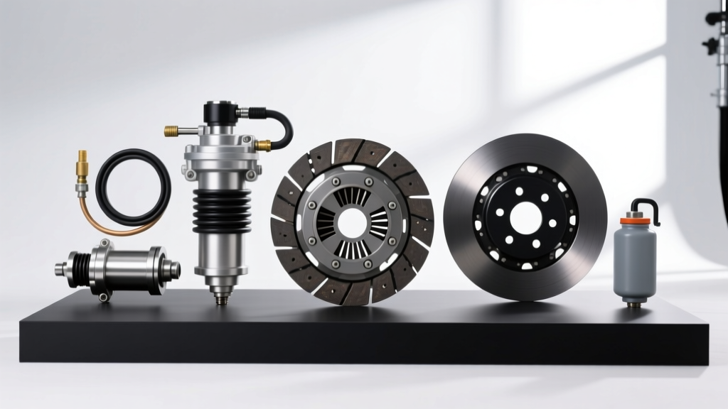
This comprehensive clutch system inspection checklist is designed for advanced DIYers and professional drivetrain technicians. It bridges the gap between mechanical wear assessment and hydraulic pressure diagnostics, culminating in a technical deep-dive on the critical process of bleeding clutch fluid to restore factory pedal feel and engagement precision.
Phase 1: Visual and Mechanical Inspection Checklist
Before introducing pressure or opening bleeder valves, a rigorous visual inspection of the hydraulic and mechanical linkages is required. Fluid loss or mechanical binding will render any bleeding procedure useless.
1. Master Cylinder and Firewall Bulkhead
- Pushrod Play: Verify 1mm to 3mm of free play at the master cylinder pushrod. Zero free play can cause the primary cup to block the compensating port, leading to hydraulic lock and premature clutch wear.
- Firewall Flex: Inspect the firewall where the master cylinder mounts. Vehicles like the 2010-2020 Ford Mustang and Chevy Camaro are notorious for firewall micro-fractures. If the firewall flexes under pedal pressure, hydraulic volume is wasted on sheet metal deformation rather than actuating the slave cylinder.
- Reservoir Cap Diaphragm: Check the rubber diaphragm under the reservoir cap. If it is torn or collapsed, the system cannot draw fluid properly, introducing cavitation and air into the lines.
2. Concentric Slave Cylinder (CSC) and Release Bearing
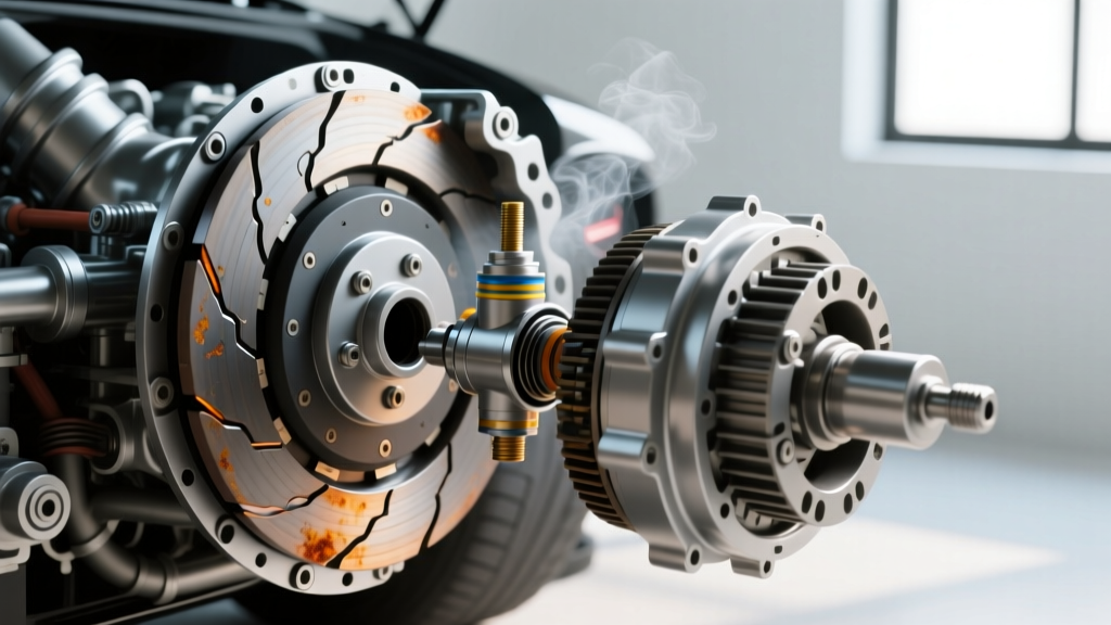
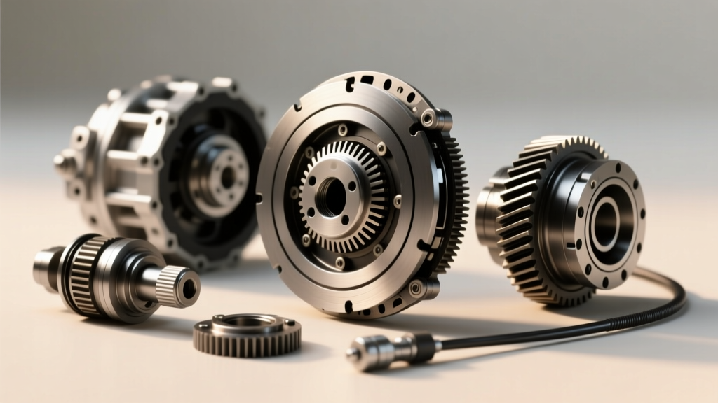
Most modern rear-wheel-drive manual vehicles utilize a Concentric Slave Cylinder (CSC) that wraps around the transmission input shaft. Inspect the weep hole at the bottom of the bell housing.
- Fluid Seepage: Any glycol-ether fluid at the bell housing drip tube indicates a failed CSC seal. For example, the FTE KN19032 CSC used in Ford MT-82 applications or the Sachs SH5007 for GM LS platforms are sealed units. If they leak internally, the transmission must be removed for replacement (typically a $300-$600 part cost, plus $800-$1,500 in labor).
- Fork and Pivot Ball Wear: On external slave setups (like older Honda K-series or Jeep AX-15 transmissions), inspect the release fork for galling at the pivot ball contact point. Apply a high-molybdenum grease (e.g., Honda Part #08798-9002) during reassembly.
Phase 2: Pedal Dynamics and Hydraulic Pressure Analysis
Pedal feel is the primary diagnostic indicator of hydraulic health. Use a steel ruler and a calibrated pedal force gauge to measure the following parameters:
- Free Play: Measure the distance the pedal travels before resistance is felt. Specification is typically 15mm to 25mm. Excessive free play indicates a worn master cylinder pushrod or air in the system.
- Reserve Travel: Depress the pedal fully to the floor mat. The distance between the fully depressed pedal and the floor should be at least 25mm. If the pedal rests on the floor, the slave cylinder is over-extending, or the clutch disc is critically worn.
- Sponginess vs. Hardness: A 'spongy' pedal almost always indicates aerated fluid or hygroscopic moisture boil. A 'hard' pedal that refuses to disengage points to a blocked hydraulic line, a seized pilot bearing, or a binding release bearing on the input shaft collar.
The Core Fix: Bleeding Clutch Fluid (Technical Deep-Dive)
When the inspection checklist points to aerated or degraded hydraulic fluid, bleeding clutch fluid becomes the necessary intervention. Brake and clutch fluids are hygroscopic, meaning they absorb ambient moisture over time. According to FMVSS 116 standards, DOT 3 and DOT 4 fluids will absorb up to 3% moisture by volume over two years. This moisture drastically lowers the fluid's boiling point, leading to vapor lock under heavy thermal loads, such as track days or stop-and-go towing.
Expert Insight: Never use DOT 5 (silicone-based) fluid in a standard hydraulic clutch system. While it does not absorb water, its high compressibility results in a permanently spongy pedal feel, and it will destroy the internal EPDM rubber seals of standard master cylinders.
Fluid Selection for Modern Applications
As of 2026, modern performance vehicles and high-end restomods frequently utilize DOT 4 Low Viscosity (LV) or DOT 5.1 fluid. DOT 4 LV ensures rapid hydraulic actuation in sub-zero temperatures, which is critical for vehicles equipped with clutch-delay valves or integrated ABS-clutch interlock systems.
| Fluid Specification | Dry Boiling Point (Min) | Wet Boiling Point (Min) | Primary Application |
|---|---|---|---|
| DOT 3 | 205°C (401°F) | 140°C (284°F) | Legacy economy vehicles, light trucks |
| DOT 4 | 230°C (446°F) | 155°C (311°F) | Standard OEM manual transmissions |
| DOT 4 LV (Class 6) | 250°C (482°F) | 165°C (329°F) | Modern cold-climate, ABS-integrated systems |
| DOT 5.1 | 260°C (500°F) | 180°C (356°F) | High-performance, heavy-duty towing, track use |
Step-by-Step Pressure Bleeding Procedure
While vacuum bleeding and manual 'pump-and-hold' methods are common, they are fundamentally flawed for clutch circuits. Vacuum bleeders can pull air past the external threads of the bleeder valve, giving the false illusion of aeration. Manual pumping often agitates the fluid, creating micro-bubbles that become trapped in the slave cylinder. The industry standard is pressure bleeding, utilizing tools like the Motive Products Power Bleeder.
Execution Protocol
- Preparation: Extract all old fluid from the master cylinder reservoir using a turkey baster or fluid extractor. Fill with fresh, sealed DOT 4 or DOT 5.1 fluid.
- Pressurization: Attach the pressure bleeder cap to the reservoir. Pump the system to exactly 15 PSI. Warning: Exceeding 20 PSI can rupture the plastic reservoir tank or blow out the master cylinder pushrod seal.
- Valve Actuation: Attach a clear vinyl tube to the CSC or external slave bleeder valve. Submerge the other end in a catch bottle partially filled with fresh fluid.
- Fluid Extraction: Using a 6-point box-end wrench or a specialized bleeder wrench, open the valve exactly 3/4 of a turn. Allow fluid to flow until it is completely free of micro-bubbles and discoloration. This typically requires 250ml to 500ml of fluid.
- Torque and Seal: Close the bleeder valve. The torque specification for most 8mm and 10mm bleeder valves is strictly 6 to 8 Nm (53 to 70 in-lbs). Over-torquing will shear the valve head or crack the slave cylinder housing.
Advanced Troubleshooting: When Bleeding Clutch Fluid Fails
If you have executed a flawless pressure bleed and the pedal remains spongy or fails to return, you are likely facing one of two catastrophic component failures:
1. Internal Master Cylinder Bypass
The primary rubber cup inside the master cylinder can harden, shrink, or score the aluminum bore. Under pressure, instead of pushing fluid down the hard line to the slave cylinder, the fluid bypasses the cup and returns directly to the reservoir. Diagnostic Test: Clamp the soft rubber hydraulic line near the master cylinder outlet. If the pedal suddenly becomes rock-hard, the master cylinder is internally bypassing and must be replaced. If the pedal remains spongy with the line clamped, the air or leak is downstream.
2. Concentric Slave Cylinder (CSC) Internal Blowout
CSC units feature an internal return spring and a sealed hydraulic chamber. If the internal O-ring fails, the piston will extend but will not generate enough hydraulic force to overcome the clutch diaphragm spring. The fluid simply circulates internally. According to FTE Automotive engineering guidelines, once a CSC loses internal hydraulic boundary integrity, it cannot be rebuilt; the transmission must be separated from the engine block for a complete CSC and release bearing assembly replacement.
Conclusion and Maintenance Intervals
A rigorous clutch system inspection checklist is the only reliable method to differentiate between mechanical wear and hydraulic failure. Bleeding clutch fluid should not be viewed merely as a repair, but as a critical preventative maintenance interval. For daily driven vehicles, flush the hydraulic circuit every 3 years or 45,000 miles. For track-driven vehicles utilizing high-RPM clutch dumps, bleed the system with high-temp DOT 5.1 fluid before every event, and inspect the CSC weep hole for thermal degradation. By adhering to exact torque specifications and utilizing pressure-bleeding methodologies, you ensure crisp, predictable clutch engagement and extend the lifespan of the entire drivetrain.