Visualizing the Hydraulic Clutch Diagram: A Beginner's Guide
If you are transitioning from driving automatics to manuals, or perhaps diving into your first DIY transmission swap, understanding the hydraulic clutch diagram is your first step toward smooth gear changes. Unlike older cable-actuated systems that rely on mechanical tension, modern manual transmissions use a closed-loop hydraulic system. This setup relies on the principle that brake fluid is incompressible, allowing your foot's input at the pedal to translate instantly into mechanical force at the transmission bell housing.
When you experience clutch engagement and disengagement issues, the problem almost always lies within the components mapped out in a standard hydraulic clutch diagram. Before we diagnose why your manual car is grinding into first gear or slipping on the highway, we need to break down the anatomy of the system.
The Core Components of the Hydraulic Circuit
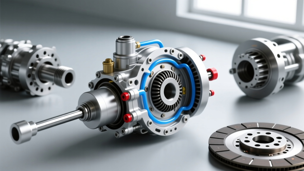
- Clutch Master Cylinder (CMC): Mounted on the firewall or pedal box, this reservoir and piston assembly converts mechanical pedal force into hydraulic pressure.
- Hard and Soft Hydraulic Lines: Steel hard lines route fluid through the chassis, while flexible rubber or braided stainless soft lines bridge the gap to the moving transmission.
- Clutch Slave Cylinder (CSC): This actuator receives the hydraulic pressure. It can be an external cylinder pushing a mechanical fork, or an internal concentric slave cylinder (CSC) that wraps directly around the transmission input shaft.
- Release (Throw-Out) Bearing & Fork: The final mechanical link that presses against the pressure plate's diaphragm springs to disengage the clutch.
Diagnosing Disengagement Issues (Clutch Drag)
Disengagement occurs when you press the pedal to the floor. The goal is to completely separate the friction disc from the flywheel so you can change gears. When this fails, you experience 'clutch drag.' Symptoms include a grinding noise when trying to shift into 1st or Reverse while stationary, or the car creeping forward even with the pedal fully depressed.
Common Causes of Incomplete Disengagement
- Air in the Hydraulic Line: Air is compressible; fluid is not. If air enters the system, your pedal stroke compresses the air bubbles instead of moving the slave cylinder. This results in a 'spongy' pedal feel and insufficient travel at the release bearing.
- Master Cylinder Pushrod Misadjustment: The pushrod connecting the pedal to the master cylinder requires a specific amount of 'free play' (typically 0.5mm to 1.0mm). If adjusted too tightly, the master cylinder's internal bypass port remains blocked, trapping pressure and preventing the clutch from fully engaging the flywheel, leading to premature wear and drag.
- Worn Internal Master Cylinder Seals: Over time, the internal rubber cups degrade. Instead of pushing fluid down the line, the fluid bypasses the seal inside the cylinder, resulting in a pedal that slowly sinks to the floor under constant pressure.
Diagnosing Engagement Issues (Slipping and Chatter)
Engagement happens when you release the pedal, allowing the pressure plate to clamp the friction disc against the flywheel. Issues here usually manifest as RPMs flaring without a corresponding increase in vehicle speed (slipping), or a violent shuddering through the chassis when taking off from a stop (chatter).
Why Your Clutch Fails to Engage Properly
- Oil Contamination: A leaking rear main engine seal or transmission input shaft seal can coat the friction material in oil. This destroys the coefficient of friction, causing severe slipping. No amount of hydraulic bleeding will fix this; the transmission must be removed.
- Glazed Friction Material: 'Riding the clutch' generates immense heat (easily exceeding 600°F at the friction surface). This heat bakes the organic resin in the clutch disc, creating a hardened, glassy surface that slips under heavy load.
- Weak Pressure Plate Springs: High-mileage pressure plates lose their clamping force. If you have upgraded your engine's torque output (e.g., adding a supercharger to a Subaru WRX or Ford Mustang GT) without upgrading the clutch, the stock pressure plate will simply be overpowered.
Expert Tip: Never use petroleum-based cleaners or compressed air to clean a clutch disc or flywheel. Petroleum leaves a residue that causes slipping, and compressed air can blow hazardous asbestos or ceramic dust into your eyes and lungs. Always use dedicated brake parts cleaner and a damp rag.
Diagnostic Chart: Symptom to Solution
Use this troubleshooting matrix to isolate your clutch system fault based on your specific symptoms.
| Symptom | Probable Component Fault | Diagnostic Test | Estimated 2026 Repair Cost |
|---|---|---|---|
| Pedal feels spongy, sits low | Air in lines / Leaking Slave | Pump pedal, hold pressure, check for fluid weeping at CSC | $60 - $150 (Bleed/External Slave) |
| Grinding into 1st/Reverse | Incomplete Disengagement | Check master cylinder pushrod free play (spec: 0.5-1.0mm) | $45 - $120 (CMC Replacement) |
| RPM flare in 3rd/4th gear | Worn Friction Disc / Glazing | Stall test in high gear (RPMs rise but speed does not) | $400 - $900 (Full Kit + Labor) |
| Chatter on take-off | Oil Contamination / Warped Flywheel | Inspect bell housing for oil leaks; check flywheel runout | $250 - $600 (Rear Main Seal + Resurface) |
Critical Specifications: Fluids, Torque, and Clearances
To repair these issues correctly, you must adhere to manufacturer specifications. Guesswork leads to repeat failures.
Hydraulic Fluid Selection
Most hydraulic clutch systems share the same fluid as the braking system. Standard applications require DOT 3 or DOT 4 brake fluid. DOT 4 is generally preferred for its higher dry boiling point (minimum 446°F / 230°C compared to DOT 3's 401°F / 205°C). For high-performance or track applications, a fluid like Castrol SRF or Motul RBF 600 is recommended to prevent fluid boil under aggressive use. Always check your reservoir cap for the specific DOT rating.
Torque Specifications
When replacing components, proper torque is vital to prevent cracking aluminum bell housings or stripping threads. While you must consult your specific service manual, here are common baseline specs for popular manual platforms:
- External Slave Cylinder Mounting Bolts (e.g., GM LS T56): 15 Nm (11 lb-ft). Over-torquing these small M6 bolts will snap them inside the aluminum transmission case.
- Concentric Slave Cylinder (CSC) Bolts (e.g., Ford MT-82): 8 Nm (71 lb-in). These are often small M5 or M6 bolts requiring an inch-pound torque wrench.
- Flywheel to Crankshaft Bolts: Typically 70-90 Nm (50-65 lb-ft) plus an additional 90-degree angle turn (Torque-to-Yield). Always use new TTY bolts and apply a drop of blue Loctite (Threadlocker 243).
Step-by-Step Hydraulic Bleeding for Beginners
If your hydraulic clutch diagram troubleshooting points to air in the system, you must bleed the lines. While gravity bleeding works in a pinch, pressure bleeding is the professional standard.
- Prepare the Master Cylinder: Clean the cap area to prevent dirt ingress. Fill the reservoir with fresh DOT 4 fluid. Do not let it run dry during the process.
- Attach the Pressure Bleeder: Use a tool like the Motive Power Bleeder, pressurized to 15-20 PSI. This forces fluid through the system without requiring a helper to pump the pedal.
- Open the Slave Bleeder Valve: Attach a clear vinyl tube to the bleeder nipple on the slave cylinder, routing the other end into a catch bottle.
- Flush the System: Open the nipple and watch the clear tube. You will see air bubbles, followed by dirty fluid, and finally a steady stream of clean, bubble-free fluid.
- Close and Verify: Tighten the bleeder nipple to 5-7 Nm. Depress the clutch pedal; it should feel firm and return crisply. Measure the slave cylinder rod travel; it should match the factory spec (usually between 12mm and 18mm depending on the application).
When to Replace the Entire Assembly
If you are already dropping the transmission to fix an internal leak or a worn friction disc, never reuse the old pressure plate or release bearing. Modern repair kits from OEM-tier manufacturers like Exedy, LuK, or Sachs include the friction disc, pressure plate, release bearing, and alignment tool in one box (often called a 'RepSet'). For hydraulic components, replacing the master and slave cylinders simultaneously as a matched set prevents the new master cylinder's higher pressure from blowing out the old slave cylinder's aging seals. For deeper transmission-specific teardown procedures, consulting resources like the Tremec Service Manuals or dedicated tech guides at Hagerty Media will provide the exact clearances and shim sizes required for your specific gearbox.
Understanding the flow of hydraulic pressure from your foot to the clutch fork demystifies manual transmission maintenance. By reading the system like a diagram, checking free play, and using the correct fluids and torque specs, you can diagnose and resolve almost any engagement or disengagement issue with confidence.