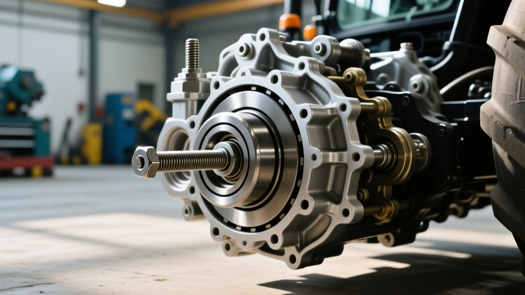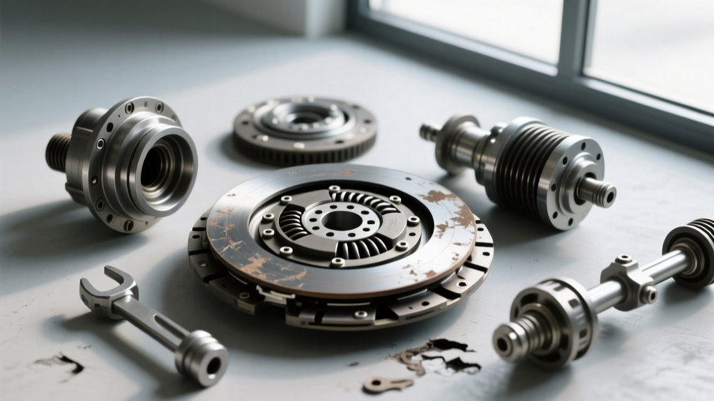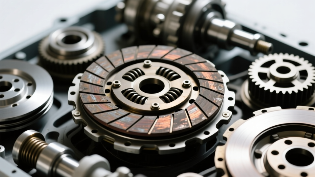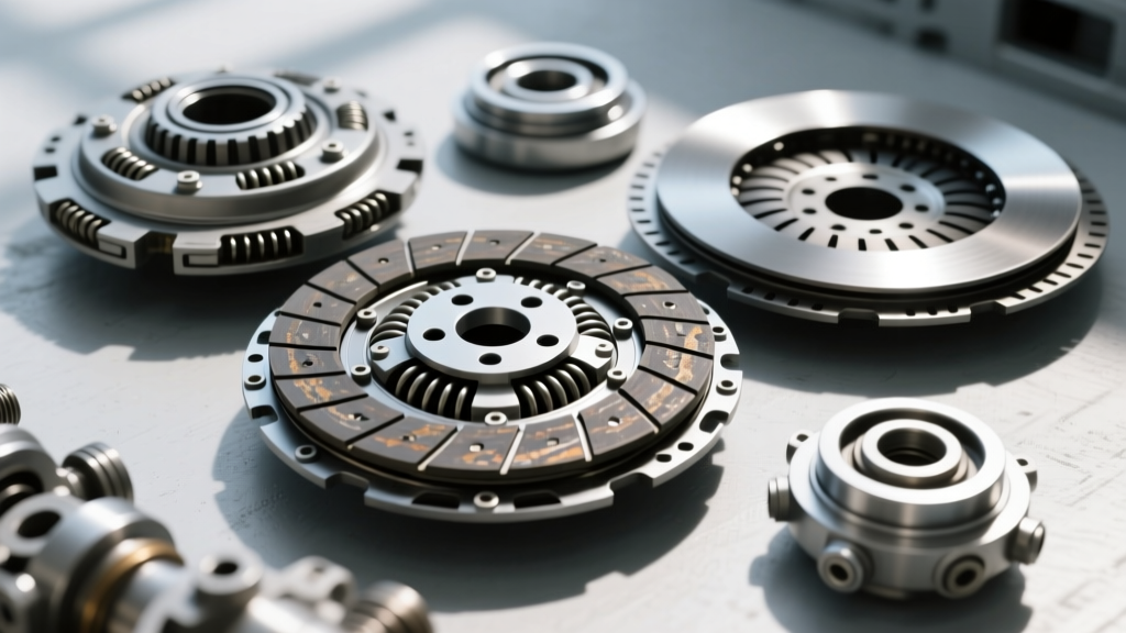
To accurately diagnose drivetrain noise, engagement issues, or torsional vibration, a technician must first answer a fundamental question: how does a manual transmission clutch work? Far from being a simple friction switch, the modern clutch assembly is a precisely calibrated torsional coupling designed to manage immense kinetic energy, dampen harmonic engine vibrations, and modulate torque transfer. In 2026, with the proliferation of high-torque turbocharged four-cylinders and advanced dual-mass flywheel (DMF) systems, understanding the underlying physics of clutch operation is mandatory for effective troubleshooting.
The Kinematics of Clutch Engagement
At its core, a manual clutch relies on the clamping force of a diaphragm spring to sandwich a friction disc between the flywheel and the pressure plate. However, the diaphragm spring operates on a non-linear, 'over-center' mechanical curve. When the pedal is depressed, the spring passes through a high-load apex before the load actually decreases near full travel. This is why pedal effort feels heaviest midway through the stroke. If the hydraulic system or cable linkage restricts full travel, the spring never crosses this apex, resulting in incomplete disengagement, gear grind, and accelerated release bearing failure.
Furthermore, the friction disc is not a solid piece of steel. It features a 'marcel spring'—a waved steel cushion layer between the friction facings—and a torsional damper hub equipped with heavy-duty coil springs and friction washers. These components absorb the violent torque spikes generated during combustion events and sudden engagement, protecting the transmission input shaft and differential gears from catastrophic shock-loading.
Phase 1: External Clutch System Inspection Checklist
Before dropping the transmission, a rigorous external inspection can isolate 60% of all clutch-related complaints. Use this checklist to evaluate the actuation system.
Hydraulic Actuation & Pedal Geometry
- Master Cylinder Pushrod Clearance: There must be a 0.020' to 0.040' (0.5mm - 1.0mm) gap between the master cylinder pushrod and the piston when the pedal is fully released. Zero clearance traps fluid, blocking the compensating port and causing the clutch to slip under high thermal loads.
- Pedal Free-Play Measurement: Measure free-play directly at the pedal pad. Most OEM specifications dictate 15mm to 25mm (approx. 0.6' to 1.0'). Excessive free-play indicates worn pivot bushings or a failing slave cylinder return spring.
- Fluid Condition & Hygroscopy: DOT 3 and DOT 4 brake fluids are hygroscopic. Moisture contamination lowers the boiling point, leading to vapor lock in the slave cylinder during heavy track use or stop-and-go traffic. Flush with fresh DOT 4 or DOT 5.1 fluid annually.
- Concentric Slave Cylinder (CSC) Bleeding: CSCs are notorious for trapping air. Standard gravity bleeding is often insufficient. Use a reverse-bleeding pressure system to force fluid from the slave cylinder back up to the master cylinder, pushing air bubbles out against their natural buoyancy.
Phase 2: Teardown and Internal Component Diagnostics
Once the transmission (e.g., a Tremec T56 Magnum or a ZF S6-650) is removed, the internal inspection begins. Do not rely on visual estimates; use precision measuring tools. Refer to the diagnostic matrix below, based on data from leading manufacturers like Exedy Global and Centerforce.
| Component | Measurement Parameter | OEM Service Limit | Diagnostic Implication of Failure |
|---|---|---|---|
| Friction Disc Lining | Thickness above rivet heads | < 0.3mm (0.012') | Rivet scoring on flywheel; severe slip under high torque. |
| Flywheel Friction Face | Dial Indicator Runout (TIR) | > 0.10mm (0.004') | Clutch chatter, uneven wear, and pedal pulsation. |
| Diaphragm Spring Fingers | Wear depth at bearing contact | > 0.6mm (0.024') | Loss of clamping load; incomplete disengagement. |
| Input Shaft Splines | Radial play with disc installed | > 0.15mm (0.006') | Clunking on engagement; marcel spring fatigue. |
| Release Bearing Collar | Surface scoring or bluing | Any thermal discoloration | Hydraulic pre-load error; riding the clutch pedal. |
Analyzing Friction Material Degradation
The color and texture of the worn friction material tell a detailed story. A glazed, mirror-like finish on an organic disc indicates chronic slip and thermal degradation, often caused by improper pedal adjustment or an oil-soaked rear main seal. Conversely, if you are inspecting a cerametallic or sintered iron disc (common in motorsport or heavy-duty towing applications), look for micro-cracking and localized hot-spots. According to tribological studies referenced by the SAE International, sintered materials can withstand surface temperatures exceeding 700°C, but they require aggressive flywheel surfaces to maintain their coefficient of friction. Machining a flywheel to a mirror finish for a sintered disc will result in immediate, violent chatter.
Phase 3: Flywheel Step Height and Machining Protocols
One of the most critical, yet frequently overlooked, aspects of clutch diagnostics is flywheel step height. The step is the distance between the flywheel's friction surface and the pressure plate mounting pad.
Expert Rule of Thumb: Push-type clutches (common in GM, Ford, and most aftermarket setups) require a positive step, typically ranging from 0.020' to 0.040'. Pull-type clutches (frequent in Subaru, Mitsubishi, and VW/Audi transverse applications) require a negative step or specific diaphragm clearance. Installing a push-type clutch on a flywheel machined flat (zero step) will result in a heavy pedal, premature diaphragm spring fatigue, and slipping under load.
Always measure the step height with a straightedge and feeler gauges before sending the flywheel to the machine shop. If the flywheel is a Dual-Mass (DMF) unit, machining is generally prohibited by OEMs due to the precise internal balancing and damping spring calibrations. DMF units exhibiting more than 15 degrees of free rotational play or visible grease leakage from the internal bearing must be replaced as a complete assembly, often costing between $800 and $1,400 for OEM parts.
Phase 4: Bellhousing Concentricity (Dial Indicating)
If you are replacing a clutch in a high-performance or heavy-duty application, checking bellhousing runout is non-negotiable. Misalignment between the engine crankshaft centerline and the transmission input shaft centerline causes catastrophic wear to the pilot bearing, input shaft, and release bearing.
- Mount a magnetic base dial indicator to the engine block or crankshaft flange.
- Position the indicator stylus against the inside bore of the bellhousing.
- Rotate the crankshaft 360 degrees and record the Total Indicator Reading (TIR).
- For modern manual transmissions like the Tremec Magnum series, the maximum allowable TIR is 0.005' (0.127mm).
If the runout exceeds 0.005', the transmission will bind, leading to difficult shifts and premature clutch disc hub failure. Correct this by installing offset dowel pins (available in 0.007', 0.014', and 0.021' offsets from specialty manufacturers) to re-center the bellhousing.
Reassembly Torque Specifications and Best Practices
Proper reassembly ensures the longevity of the entire drivetrain. Always use a thread-locking compound on flywheel bolts, as they are subjected to immense shear forces. Below are standard torque baselines (always verify with the specific OEM service manual):
- Flywheel to Crankshaft (GM LS V8, 3/8' bolts): 74 lb-ft with Red Loctite 271.
- Flywheel to Crankshaft (Honda K-Series, M12 bolts): 76 lb-ft (yield bolts should be replaced).
- Pressure Plate to Flywheel (M8x1.25 bolts): 22 to 25 lb-ft, tightened in a crisscross star pattern in three progressive steps to prevent warping the pressure plate cover.
- Bellhousing to Engine Block: 35 to 50 lb-ft depending on fastener grade.
Summary: The Diagnostic Mindset
Understanding how a manual transmission clutch work is about recognizing the delicate balance of mechanical leverage, hydraulic pressure, and material science. By adhering to this technical inspection checklist—verifying hydraulic clearances, measuring flywheel step heights, and dial-indicating the bellhousing—you transition from a parts-swapper to a true drivetrain diagnostician. Whether you are troubleshooting a daily-driver commuter car or rebuilding a 1,200 lb-ft twin-disc setup for a dedicated track car, precision measurement is the only path to a reliable, chatter-free engagement.