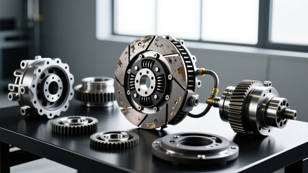
The Engineering Reality of Clutch Friction Plate Degradation
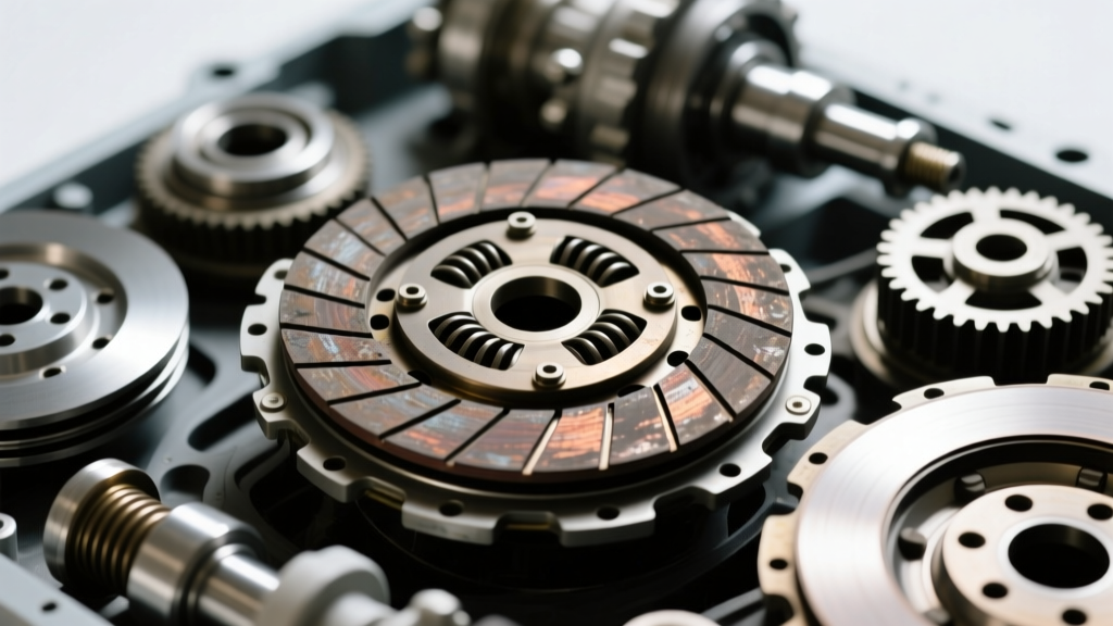
The clutch friction plate is the primary sacrificial component in any manual or dual-clutch drivetrain. It serves as the torsional bridge between the engine's flywheel and the transmission input shaft. While many DIY mechanics rely on subjective pedal feel or audible slipping to diagnose wear, professional drivetrain diagnostics demand quantitative measurement. As of 2026, the widespread integration of Self-Adjusting Clutch (SAC) mechanisms and wet Dual-Clutch Transmissions (DCTs) means that traditional "slippage" symptoms are often masked by hydraulic compensation until catastrophic failure occurs.
Understanding the exact wear limits, material degradation patterns, and collateral damage indicators of a clutch friction plate is critical for accurate diagnosis. Guessing the remaining lifespan of a friction disc frequently leads to scored flywheels, shattered pressure plates, and damaged input shaft bearings.
Metallurgy and Friction Material Classifications
Before measuring wear, technicians must identify the friction material compound, as the coefficient of friction (μ) and thermal degradation points vary wildly. According to SAE International technical standards, friction materials are categorized by their organic, semi-metallic, or sintered composition.
- Organic (Full-Faced): Composed of fiberglass, Kevlar, and phenolic resins. Offers smooth engagement (μ ≈ 0.30 - 0.38) but glazes rapidly above 250°C (482°F).
- Cerametallic (Puck/Sprung): Utilizes copper and iron ceramics. High thermal threshold (up to 450°C) but requires higher clamp loads, accelerating flywheel wear.
- Sintered Iron: Used in dedicated drag and motorsport applications. Extremely aggressive (μ ≈ 0.55 - 0.65), operates effectively at high temperatures, but completely unsuitable for street-driven low-speed engagement.
Quantitative Wear Limits and Measurement Protocols
Visual inspection is insufficient. A friction plate must be measured using digital calipers or a micrometer. The critical measurement is the rivet depth clearance—the distance between the friction material surface and the top of the rivet head.
| Material Type | New Thickness (Avg) | Minimum Rivet Depth | Max Thermal Limit |
|---|---|---|---|
| Standard Organic | 8.5 mm | 0.30 mm (0.012") | 250°C (482°F) |
| Heavy-Duty Organic | 9.5 mm | 0.40 mm (0.015") | 300°C (572°F) |
| Cerametallic (Puck) | 10.0 mm | 0.50 mm (0.020") | 450°C (842°F) |
| Sintered Iron | 4.5 mm | 0.25 mm (0.010") | 600°C+ (1112°F+) |
Critical Warning: If the rivet depth measures less than 0.30 mm, the clutch friction plate is past its service life. Continued operation will result in the steel rivets gouging the cast iron or billet aluminum flywheel, transforming a $400 clutch replacement into a $1,200+ drivetrain overhaul.
Diagnosing Self-Adjusting Clutch (SAC) Systems
Modern European and late-model domestic vehicles frequently utilize LuK Self-Adjusting Clutch (SAC) technology. The SAC pressure plate features a mechanical wear-compensation ring that automatically adjusts the diaphragm spring position as the clutch friction plate thins.
SAC Failure Indicators
Because the SAC maintains a consistent clutch pedal bite point throughout the friction plate's life, drivers rarely notice gradual wear. The definitive diagnostic sign of a maxed-out SAC friction plate is a sudden, uncorrectable change in pedal geometry. When the friction material reaches its absolute limit, the adjustment ring hits its mechanical stop. At this point, the diaphragm spring fingers over-center, resulting in a pedal that either drops to the floor without disengaging or requires immense physical force to depress.
Diagnostic Step: With the transmission removed, inspect the SAC adjustment ring. If the ramp gears are bottomed out against the physical stopper tabs on the pressure plate housing, the friction plate is definitively at end-of-life, regardless of how much visual friction material appears to remain.
Dual-Clutch Transmission (DCT) Friction Pack Clearances
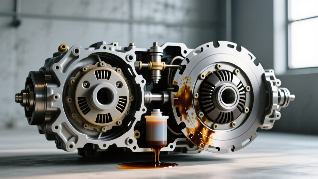
In wet DCT applications, such as the VW/Audi DQ250 (02E) or the Porsche PDK, the clutch friction plate takes the form of multiple internal and external splined friction discs submerged in specialized DCT fluid. Diagnosing wear here requires measuring the clutch pack clearance, not individual disc thickness.
DQ250 (02E) Wet Clutch Diagnostic Procedure
- Mount a dial indicator on the transmission bellhousing, resting the probe on the outer clutch drum.
- Apply a specific downward force (usually via a specialized factory tool or calibrated dead weight) to compress the clutch pack.
- Zero the dial indicator.
- Release the pressure and measure the total upward travel (clearance).
For the DQ250 6-speed wet clutch, the factory specification for total pack clearance typically ranges between 1.35 mm and 1.85 mm, depending on the exact revision of the friction plates and the number of shims installed. A clearance exceeding 2.0 mm indicates severe friction material wear, leading to delayed shifts, harsh engagements, and eventual mechatronic solenoid over-travel faults.
Thermal Degradation: Glazing and Martensite Formation
Wear is not always a loss of physical thickness; it can also be a loss of friction coefficient due to thermal abuse. When a driver "rides" the clutch or performs repeated high-RPM launches, the friction surface exceeds its thermal threshold. The organic resins melt and migrate to the surface, creating a hardened, glass-like layer known as glazing.
Glazing is diagnosed by a distinct high-frequency chatter during engagement, even if the pedal travel and rivet depths are within specification. Furthermore, the excessive heat transfers through the friction plate into the flywheel. On cast iron flywheels, localized extreme heat followed by rapid cooling (from ambient air or clutch fluid) alters the crystalline structure of the iron, forming martensite. These hard, brittle "hot spots" cannot be machined away on a standard brake lathe and will instantly destroy a new clutch friction plate through aggressive, uneven wear.
Collateral Damage: Bellhousing Runout and Input Shaft Wear
When diagnosing a prematurely worn clutch friction plate, technicians must investigate the root cause. Uneven wear—where one side of the friction disc is worn down to the rivets while the opposite side has 3 mm of material remaining—is almost always caused by excessive bellhousing runout.
According to Tremec engineering specifications for manual transmissions like the T56 Magnum, the bellhousing bore must be concentric with the engine crankshaft centerline. The maximum allowable Total Indicator Reading (TIR) is 0.005 inches (0.127 mm). If the bellhousing is misaligned, the transmission input shaft binds within the pilot bearing, forcing the clutch friction plate to wobble during engagement. This wobble causes localized, catastrophic wear on the friction material and eventually snaps the torsional damper springs housed within the disc's hub.
Mandatory Installation Torque Specifications
When replacing a worn friction plate, precise torque sequences are mandatory to prevent pressure plate warping, which mimics the symptoms of a worn disc:
- Flywheel to Crankshaft (e.g., GM LS-Series): 74 Nm (55 lb-ft) + 90-degree angle turn.
- Pressure Plate to Flywheel (M8 Bolts): 25 Nm (18 lb-ft), applied in a star-pattern sequence in three incremental steps (10 Nm, 18 Nm, 25 Nm) to ensure even diaphragm spring tension.
- Bellhousing to Engine Block: 50 Nm (37 lb-ft), followed by dial-indicator verification of the 0.005" TIR limit before mating the transmission.
By shifting from subjective symptom-chasing to objective, measurement-based diagnostics, drivetrain specialists can accurately determine the exact lifespan remaining in a clutch friction plate, preventing secondary component failures and ensuring optimal power transfer.