The Evolving Landscape of Class 8 Drivetrains
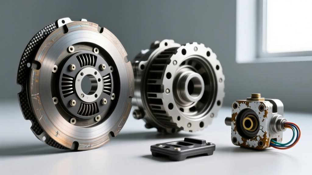
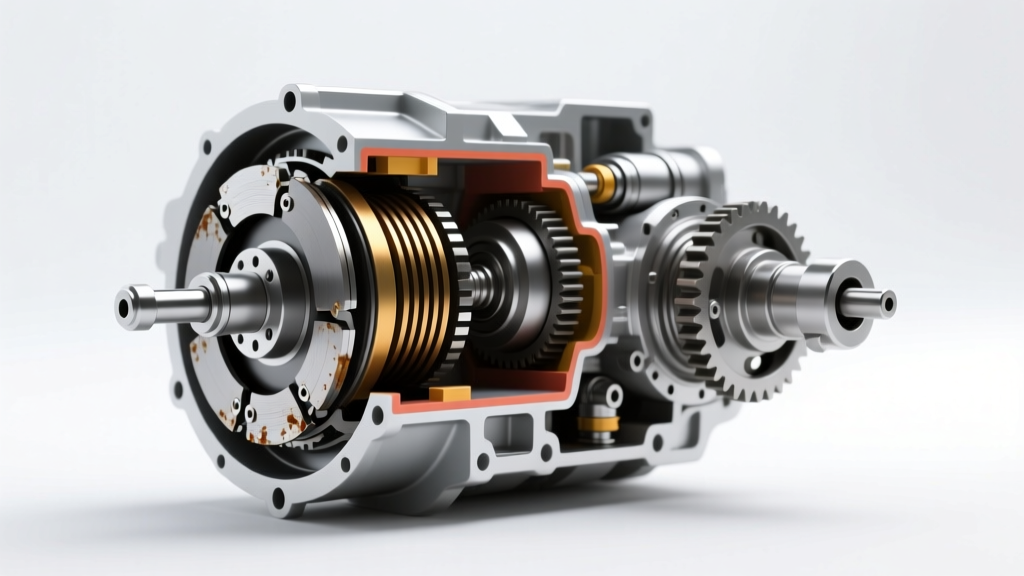
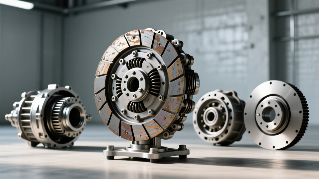
As we navigate the 2026 freight landscape, heavy-duty and commercial vehicles are subjected to unprecedented torque loads and severe-duty cycles. While automated manual transmissions (AMTs) like the ZF Traxon and Eaton Endurant have captured significant market share, traditional manual transmissions—such as the legendary Eaton Fuller RTLO-18918B—remain the backbone of heavy-haul, logging, and specialized vocational fleets. These drivetrains routinely handle engine outputs exceeding 2,050 lb-ft of torque, transferring that power through massive 15.5-inch twin-plate diaphragm spring clutches.
However, the immense clamping force required to manage this torque introduces severe mechanical stress on the actuation system. When drivers report heavy pedal effort, incomplete disengagement, or premature clutch brake failure, fleet managers often misdiagnose the root cause, immediately condemning the internal clutch assembly. In reality, the failure frequently originates at the driver's interface. Upgrading to a reinforced universal clutch pedal assembly is increasingly recognized as a critical performance and diagnostic intervention for commercial trucks suffering from chronic actuation symptoms.
Pinpointing Critical Heavy-Duty Clutch Symptoms
Diagnosing clutch problems in Class 8 vehicles requires a methodical approach that separates internal friction component wear from hydraulic and mechanical actuation faults. According to service guidelines from the Eaton Vehicle Group, technicians must evaluate the following primary symptoms before pulling the transmission:
1. Clutch Brake Squeeze Failure
The clutch brake is essential for stopping the input shaft's rotation to allow smooth gear engagement from a standstill. The diagnostic test involves measuring the 'squeeze'—the distance the pedal travels after the clutch brake engages. In a properly adjusted heavy-duty system, the clutch brake should engage when the pedal pad is exactly 1/2-inch to 3/4-inch from the firewall. If the pedal rests against the firewall before the brake engages, or if the squeeze exceeds 1 inch, the system suffers from hydraulic bypass, air ingress, or severe firewall flex.
2. High-Speed Engagement Chatter
Chatter during engagement under load is often blamed on oil contamination on the friction discs. However, in heavy-duty applications, chatter is frequently caused by failing torsional dampers in the clutch disc or, critically, a flexing pedal assembly that fails to release the clutch smoothly. When the pedal pivot degrades, the release bearing applies uneven pressure to the diaphragm spring fingers, causing a cyclic grabbing and slipping effect.
3. Pedal Fade and Phantom Disengagement
During long descents or stop-and-go traffic, a pedal that slowly sinks to the floor indicates master cylinder internal seal bypass. In commercial trucks, the master cylinder is often mounted directly to the sheet-metal firewall. Under the 300+ lbs of pedal effort required for a heavy-duty clutch, the firewall physically bows backward, altering the pedal ratio and causing a 'spongy' or fading sensation that mimics internal hydraulic failure.
Why OEM Pedal Assemblies Fail in Severe-Duty Cycles
Original Equipment Manufacturer (OEM) pedal assemblies in many legacy and current commercial trucks utilize composite materials, plastic pivot bushings, and stamped steel brackets to save weight and reduce assembly line costs. While adequate for standard highway cruising, these components rapidly degrade in vocational environments.
The pivot pin in a standard OEM assembly is typically a mild steel rod riding in a nylon or Delrin bushing. Under the extreme lateral loads generated by a 15.5-inch clutch, these bushings ovalize. This wear introduces lateral play, which destroys the precise 6:1 mechanical pedal ratio required to actuate the clutch. Furthermore, the firewall mounting points are prone to stress cracking. Once the firewall flexes, the master cylinder pushrod is no longer actuated in a perfectly linear path, leading to premature wear on the master cylinder's internal piston seals and eventual fluid bypass.
The Performance Solution: Universal Clutch Pedal Retrofits
To permanently resolve these actuation symptoms, heavy-duty performance shops and specialized fleet maintenance divisions are turning to billet aluminum universal clutch pedal assemblies. Originally developed for motorsport and heavy machinery applications, these universal kits are adapted for Class 8 cabs to eliminate firewall flex and restore exact hydraulic geometry.
A high-quality universal pedal box relocates the master cylinder to a reinforced, rigid bracket that ties directly into the truck's structural steel dashboard framework or A-pillar, completely bypassing the fragile sheet-metal firewall. By utilizing CNC-machined 6061-T6 aluminum pivot arms and sealed needle-roller bearings, the universal clutch pedal maintains a perfect 6:1 or 7:1 mechanical ratio regardless of pedal effort. This ensures that the hydraulic master cylinder receives a perfectly linear stroke, maximizing fluid displacement to the slave cylinder and guaranteeing full clutch disengagement and precise clutch brake actuation.
Technical Specifications and Hardware Requirements
When selecting and installing a universal clutch pedal system for a commercial vehicle, matching the master cylinder bore size to the slave cylinder volume is critical. Heavy-duty trucks typically utilize large-diameter slave cylinders to move the heavy release forks of SAE #1 and #2 bellhousings.
| Specification | OEM Plastic/Stamped Assembly | Performance Universal Clutch Pedal |
|---|---|---|
| Pivot Mechanism | Nylon/Delrin Bushing | Sealed Needle-Roller Bearings |
| Mounting Base | Direct to Sheet-Metal Firewall | Structural Steel Cab Framework / Billet Bracket |
| Pedal Ratio | 5.5:1 (Degrades with flex) | 6.5:1 (Fixed, Linear Actuation) |
| Master Cylinder Compatibility | Proprietary Push-rod Plastic | Standard AN3 Fittings (e.g., Wilwood 1.00" Bore) |
| Estimated Pedal Effort (15.5" Clutch) | 110 - 140 lbs (Increases with wear) | 85 - 95 lbs (Consistent) |
Step-by-Step Diagnostic and Installation Framework
Retrofitting a universal clutch pedal into a heavy-duty cab requires precision measurement and strict adherence to torque specifications. Below is the professional framework for executing this upgrade.
- Baseline Hydraulic Verification: Before removing the OEM pedal, pressure-test the hydraulic system. Connect a gauge to the slave cylinder bleeder. Peak pressure during a pedal stroke should reach 1,200 to 1,500 PSI. If pressure is low, rebuild the slave cylinder before installing the new pedal.
- Structural Bracket Fabrication: Fabricate a mounting plate from 1/4-inch hot-rolled steel. Bolt this plate to the cab's structural A-pillar or heavy-gauge dash support using M10 Grade 8.8 hardware. Torque structural bolts to 45 lb-ft with medium-strength threadlocker.
- Universal Pedal Mounting: Secure the billet universal clutch pedal assembly to the fabricated bracket. Ensure the pivot axis is perfectly parallel to the firewall to prevent lateral binding on the master cylinder pushrod.
- Master Cylinder Integration: Install a heavy-duty master cylinder (such as a 1-inch or 1-1/8-inch bore unit). Connect the hydraulic lines using -3 AN stainless steel braided hoses and AN3 fittings. Torque AN3 aluminum fittings to 12-15 lb-ft using a crowfoot wrench to avoid rounding.
- Pedal Pad and Free-Play Adjustment: Adjust the master cylinder pushrod to achieve exactly 1/8-inch to 1/4-inch of free-play at the top of the pedal stroke. This free-play is non-negotiable; without it, the master cylinder piston will not fully retract, blocking the compensating port and causing the clutch to slip under high thermal expansion.
Bleeding Protocols for Heavy-Duty Systems
Commercial truck hydraulic lines often span over 10 feet from the cab to the bellhousing, making air removal notoriously difficult. Gravity bleeding is insufficient for heavy-duty systems. Technicians must utilize a reverse-bleeding or pressure-bleeding protocol. Connect a pressure bleeder to the master cylinder reservoir, pressurized to exactly 25-30 PSI. Open the slave cylinder bleeder valve and allow fluid to flow until it is completely free of micro-bubbles. Using a high-quality synthetic DOT 4 fluid with a dry boiling point exceeding 500°F (260°C) is recommended to resist vapor lock in high-ambient-temperature vocational environments.
Sourcing and Cost Analysis for Fleet Managers
Fleet managers must weigh the upfront cost of a universal clutch pedal retrofit against the downtime costs of a misdiagnosed clutch replacement. Dropping a heavy-duty transmission and replacing a 15.5-inch twin-plate clutch assembly typically costs between $4,500 and $7,500 in parts and labor, not including the $1,500+ per day cost of an out-of-service truck.
A complete, heavy-duty universal clutch pedal kit, including the billet pedal assembly, structural mounting brackets, and a high-volume master cylinder, ranges from $850 to $1,400. Installation labor typically requires 4 to 6 hours. By addressing the root cause of firewall flex and pivot degradation, fleets can extend the service life of the internal clutch friction components by up to 30%, as the clutch is consistently and fully engaged and disengaged without mechanical interference.
For further reading on commercial drivetrain maintenance and clutch actuation specifications, fleet technicians should consult the ZF Commercial Vehicle Solutions documentation and review the latest service bulletins from the Technology & Maintenance Council (TMC). Upgrading to a universal system is not merely a comfort modification; it is a vital diagnostic correction that ensures the drivetrain operates as engineered, safeguarding uptime and maximizing payload efficiency.