The Diagnostic Dilemma: Mechanical Wear vs. Electronic Gremlins
When diagnosing manual transmission drivability issues in modern vehicles, technicians and enthusiasts often face a critical crossroads: is the clutch friction assembly reaching the end of its mechanical lifespan, or is an electronic sensor skewing the ECU's behavior? In the era of drive-by-wire throttles and active rev-matching, the clutch pedal position switch (CPPS) plays a massive role in how the powertrain control module (PCM) manages engine torque during gear changes. Misinterpreting a failing CPPS as a slipping friction disc or a worn pressure plate can lead to unnecessary transmission drops, costing upwards of $1,200 in wasted labor and parts.
This technical deep-dive explores the exact lifespan indicators of mechanical clutch components and contrasts them with the electrical failure modes of the clutch pedal position switch. By the end of this guide, you will possess a definitive diagnostic framework to isolate the root cause of erratic pedal feel, engagement issues, and ECU torque-limiting faults.
The Evolution and Role of the Clutch Pedal Position Switch
Historically, the switch located on the clutch pedal bracket served a single, rudimentary purpose: a starter interlock to prevent the engine from cranking while in gear. However, in modern platforms—ranging from the Mazda Skyactiv-MT to the Tremec TR-6060 equipped Chevrolet Camaro SS—the CPPS is a critical data input for the PCM.
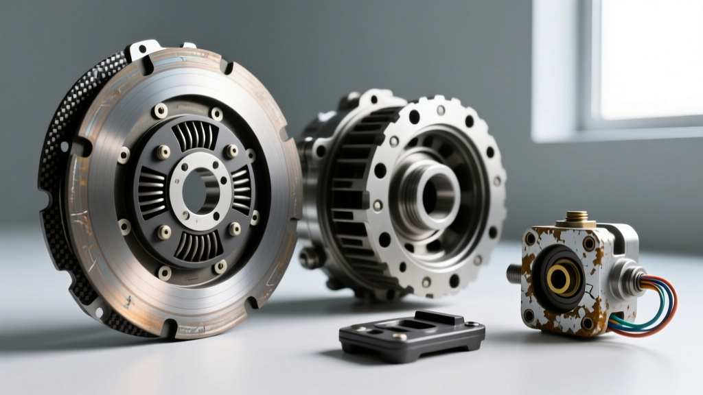
Modern CPPS units are typically 3-wire or 4-wire Hall-effect sensors or potentiometers rather than simple binary microswitches. They provide real-time pedal travel data to the ECU, enabling several vital functions:
- Cruise Control Cancellation: Disengaging the throttle mapping the moment the pedal is depressed by even 5%.
- Active Rev-Matching: Calculating the exact engine RPM rise required for seamless downshifts based on pedal depression speed.
- Torque Limiting: Softening engine torque output during the friction zone to prevent driveline shock and axle hop.
- Idle Air Control: Anticipating load changes as the clutch engages to prevent stalling.
When the CPPS fails or falls out of calibration, the ECU may default to a limp-mode torque map, cut cruise control, or cause erratic idle surges. To an untrained driver, this abrupt change in engine response feels exactly like a clutch disc that is slipping or failing to engage smoothly.
True Mechanical Clutch Wear: Lifespan Indicators and Measurements
Before condemning the electronics, a rigorous mechanical inspection is required. True clutch wear presents with specific, measurable physical degradation. According to engineering standards outlined by SAE International, friction materials degrade predictably based on thermal cycling and shear forces.
Key Mechanical Wear Metrics
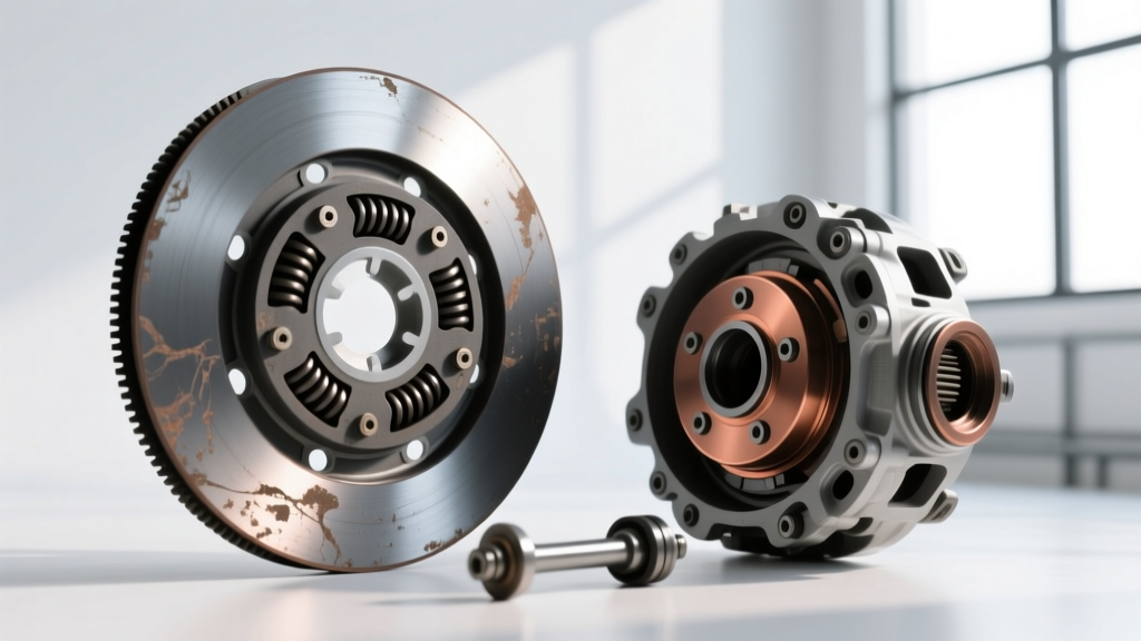
- Friction Disc Thickness: A new OEM organic clutch disc (e.g., Sachs or Exedy) typically measures between 9.0mm and 10.5mm at the friction marcel springs. The absolute service limit is usually 5.0mm to 6.0mm. If the disc measures below 6.0mm, the dampening springs are at risk of contacting the flywheel, causing severe chatter and metallic grinding.
- Flywheel Runout: Using a dial indicator, measure the lateral runout of the flywheel friction surface. The maximum allowable runout for most single-mass and dual-mass flywheels is 0.005 inches (0.127mm). Excessive runout causes localized hot spots, leading to premature glazing and a spongy pedal feel.
- Pressure Plate Finger Height: As the disc wears, the diaphragm spring fingers move closer to the release bearing. If the fingers are worn or bent beyond 0.030 inches of variance, the clutch will not fully disengage, mimicking a hydraulic master cylinder failure.
- Pedal Free-Play: Mechanical and hydraulic linkages require 0.75 to 1.25 inches of free-play at the pedal pad. A lack of free-play keeps the release bearing pre-loaded against the diaphragm spring, accelerating wear and causing high-RPM slipping.
Comparative Diagnostic Matrix: CPPS vs. Friction Disc Wear
To streamline your troubleshooting process, use the following matrix to differentiate between mechanical end-of-life symptoms and CPPS electrical faults. You can cross-reference replacement parts and pricing via databases like RockAuto to understand the financial stakes of a misdiagnosis.
| Symptom / Behavior | Mechanical Wear Indicator | CPPS / Electrical Fault |
|---|---|---|
| Engine RPM flares without proportional vehicle acceleration. | High probability. Friction material is glazed or worn past 6.0mm limit. | Low probability. ECU may limit torque, but rarely causes physical slip under heavy load. |
| Cruise control randomly disengages on flat highways. | Not related to mechanical friction components. | High probability. Switch vibration or internal open-circuit triggers safety cutoff. |
| Erratic idle surges or stalling when coming to a stop. | Possible if clutch is dragging due to warped flywheel. | High probability. ECU receives false 'pedal depressed' signal, altering idle air mapping. |
| Starter motor refuses to crank despite pedal fully depressed. | Not related to friction disc or pressure plate. | Definitive CPPS or clutch interlock switch failure (open circuit). |
| Harsh engagement or axle hop during 1st-to-2nd gear shifts. | Possible broken marcel springs or oil contamination on the disc. | Possible. ECU fails to execute torque-reduction mapping during the shift event. |
Step-by-Step CPPS Testing and Replacement Specs
If the mechanical metrics check out, pivot your diagnostic focus to the clutch pedal position switch. Testing requires a digital multimeter (DMM) and access to the under-dash pedal bracket.
Multimeter Testing Protocol
- Identify the Wiring: Locate the switch on the clutch pedal pivot bracket. Modern 3-wire switches will have a 5V Reference wire, a Signal Return wire, and a Sensor Ground wire.
- Backprobe the Connector: With the key in the 'ON' position (engine off), backprobe the 5V reference wire. You should read exactly 4.8V to 5.1V. If you read 0V, check the PCM fuse and wiring harness for chafing against the steering column.
- Signal Sweep Test: Connect the DMM to the Signal Return wire. Slowly depress the clutch pedal through its entire range of motion. The voltage should sweep smoothly (e.g., from 4.2V down to 0.8V). Any sudden drops to 0V or spikes to 5V indicate dead spots in the internal potentiometer or Hall-effect sensor.
- Binary Interlock Check: If your vehicle uses an older 2-wire starter interlock switch, set the DMM to continuity mode. The circuit should be open (OL) at rest, and show near 0.00 ohms of resistance only when the pedal is fully depressed to the floor mat.
Replacement Torque Specs and Part Data
When replacing the CPPS, precision is paramount. An improperly torqued bracket will alter the pedal geometry, ruining the ECU's rev-matching calibration. Common replacement part numbers include the Standard Motor Products SLS-214 or the Dorman 902-303, typically retailing between $18 and $45 depending on the application.
- Bracket Mounting Nuts: Torque to 15-20 Nm (11-15 lb-ft). Over-torquing can warp the plastic switch housing, causing internal binding.
- Switch Plunger Adjustment: Many modern CPPS units feature a ratcheting self-adjusting plunger. Pull the plunger out to its maximum extension before installation. As you bolt the bracket to the pedal stop, the pedal will push the plunger in, setting the exact mechanical baseline.
- ECU Relearn Procedure: On vehicles with active rev-matching (e.g., Nissan 370Z, Ford Mustang GT), replacing the switch requires a PCM pedal-position relearn. This is typically done by turning the ignition to 'ON', depressing the pedal fully five times within ten seconds, and cycling the key off.
'Never replace a $600 clutch kit and drop a transmission without first spending 15 minutes verifying the $25 clutch pedal position switch circuit and hydraulic free-play.' - Master Transmission Diagnostic Principle
Conclusion: Trust the Data, Not Just the Pedal Feel
The tactile feedback of a manual transmission is deeply ingrained in enthusiast culture, but human perception is easily fooled by electronic throttle interventions. By systematically measuring friction disc thickness, flywheel runout, and hydraulic free-play, you establish a baseline of mechanical truth. If the physical hardware is within SAE tolerances, the clutch pedal position switch and its associated PCM mapping must be scrutinized. Armed with a multimeter and this diagnostic matrix, you can confidently separate genuine end-of-lifespan clutch wear from modern electronic sensor faults, saving thousands of dollars in misdirected repair bills.