The 2026 Heavy-Duty Ecosystem: Where Auxiliary HVAC Meets Drivetrain Logic
In the modern landscape of Class 8 commercial trucking, the boundary between auxiliary comfort systems and core drivetrain components has completely dissolved. Fleet managers and performance upfitters are increasingly installing high-capacity HVAC systems, auxiliary power units (APUs), and heavy-duty PTO (Power Take-Off) drives to support advanced sleeper cabs and mobile worksite equipment. However, this integration creates a complex diagnostic web. When a commercial vehicle experiences drivetrain clutch slippage, PTO disengagement, or automated manual transmission (AMT) faults, the root cause is frequently buried in the auxiliary electrical circuits. Specifically, understanding the ac clutch relay diagram is no longer just an HVAC repair task—it is a critical step in diagnosing heavy-duty drivetrain clutch problems and executing high-performance electrical upgrades.
Modern Engine Control Modules (ECMs) in platforms like the Detroit DD15 or Cummins X15 actively monitor the amperage draw of all electromagnetic clutches, including the AC compressor, the engine fan clutch, and the driveline PTO clutch. If an upgraded AC compressor clutch coil begins to short or draw excessive current due to a failing relay, the ECM will often trigger a protective derate. This derate can disable the Eaton Fuller AMT clutch actuator or disengage the PTO clutch pack to protect the alternator and ECM drivers from catastrophic overcurrent events. Consequently, a simple HVAC relay fault can perfectly mimic a catastrophic transmission clutch failure.
The Intersection of Auxiliary HVAC and Drivetrain Clutch Diagnostics
When upgrading a heavy-duty truck for extreme environments—such as adding a Bergstrom or Red Dot high-output HVAC system for desert logging operations—the electrical load profile of the vehicle changes dramatically. The AC compressor clutch is typically engaged via a heavy-duty 12V or 24V relay controlled by the ECM or a dedicated climate control module.
Why the AC Clutch Relay Diagram is Your Blueprint
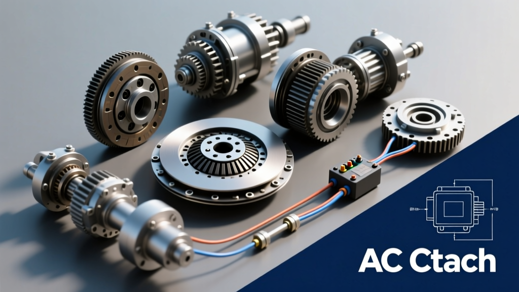
To properly isolate a drivetrain clutch fault from an auxiliary electrical fault, technicians must consult the vehicle-specific ac clutch relay diagram. This schematic reveals the control side (ECM pinout, ground paths, and idle-up request circuits) and the load side (battery feed, fuse ratings, and the electromagnetic coil). In heavy-duty applications, the AC clutch relay is often wired in parallel with the engine fan clutch relay and the PTO enable relay. A voltage drop or backfeed across a sticking AC clutch relay can send errant 12V/24V signals back into the ECM's PTO enable circuit, causing the drivetrain PTO clutch to chatter, slip, or fail to engage entirely under load.
Common Heavy-Duty Clutch Failures Misdiagnosed as ECM Faults
Before tearing down an Allison 4000 series transmission or an Eaton Advantage AMT to inspect the physical clutch packs, performance upfitters must rule out electromagnetic interference and relay-induced voltage drops. Below are the most common scenarios where HVAC electrical faults manifest as heavy-duty drivetrain clutch problems.
Electromagnetic Coil Burnout vs. Drivetrain PTO Slippage
A standard 12V heavy-duty AC clutch coil (such as the Red Dot RD-5-10860-0P) typically draws between 3.5 and 4.5 amps. When the internal windings degrade due to heat and vibration, resistance drops, and amperage spikes. The ECM detects this overcurrent event (often logging SPN 3719 - AC Clutch Circuit Overcurrent). To protect the main power bus, the ECM may cut power to the PTO clutch solenoid, resulting in sudden PTO slippage while operating winches or hydraulic pumps. Technicians frequently misdiagnose this as a worn PTO clutch pack, leading to unnecessary $3,000+ drivetrain teardowns when the actual fault is a $45 relay and a $180 AC coil.
Heavy-Duty Clutch Upgrade & Diagnostic Cost Matrix
Understanding the financial and technical scope of these interconnected systems is vital for fleet performance upgrades. The table below outlines the real-world costs, part numbers, and specifications for addressing these cross-system faults.
| Component / System | OEM / Upgrade Part Number | Resistance / Spec | Avg. Cost (2026) |
|---|---|---|---|
| Heavy-Duty AC Clutch Coil | Red Dot RD-5-10860-0P | 3.0 - 4.0 Ohms | $160 - $220 |
| High-Amp Upgrade Relay | Bosch HEV800 Series (75A) | Coil: 70 Ohms | $45 - $85 |
| Drivetrain PTO Clutch Pack | Eaton K-3851 Friction Kit | 0.030" Wear Limit | $850 - $1,400 |
| ECM Relay Harness Upgrade | Custom 10 AWG PTC Harness | Max 2mV Drop | $450 - $750 |
| Full AMT Clutch Actuator | Eaton Gen 2 AMT Actuator | N/A (Calibrated) | $2,200 - $3,500 |
Step-by-Step Relay Circuit Troubleshooting for Fleet Upgrades
When a Class 8 truck presents with PTO chatter or AMT clutch engagement delays, follow this rigorous diagnostic protocol utilizing a digital multimeter (DMM) and a PICO TA4000 automotive oscilloscope to read the ac clutch relay diagram signals in real-time.
Testing the Relay and Coil Resistance
First, isolate the AC compressor clutch coil. Disconnect the harness and measure the resistance across the coil terminals. A reading below 2.5 Ohms indicates a shorted coil that will inevitably trip the ECM's overcurrent protection, potentially disabling the drivetrain PTO clutch. Next, test the relay control circuit. With the ignition on and the HVAC demanding cooling, probe the ECM control wire. You should see a clean pulse-width modulated (PWM) signal or a solid ground path. If the voltage fluctuates wildly, the ECM driver may be damaged from previous relay backfeed.
Air Gap and Pulley Torque Specifications
If the electrical side of the ac clutch relay diagram checks out, the issue may be mechanical drag on the auxiliary system causing the engine to bog down, which the AMT interprets as a clutch slip condition. When reinstalling or upgrading the heavy-duty AC compressor, precise mechanical tolerances are mandatory:
- Clutch Air Gap: Must be set precisely between 0.020" and 0.030" using a feeler gauge. An air gap that is too wide will cause the coil to overheat and draw excess amperage; an air gap that is too narrow will cause constant drag and premature bearing failure.
- Pulley Nut Torque: Torque the compressor clutch hub nut to exactly 65 lb-ft (88 Nm) using a thread-locking compound to prevent harmonic loosening at high idle.
- Mounting Bolts: The heavy-duty compressor mounting brackets must be torqued to 35 lb-ft (47 Nm) to maintain alignment with the multi-ribbed serpentine belt, preventing lateral loads that destroy the clutch bearing.
Performance Upgrades: High-Amp Relays and Auxiliary PTO Management
For commercial fleets operating in extreme conditions, relying on OEM 40-amp relays for high-capacity aftermarket AC compressors is a recipe for drivetrain diagnostic nightmares. Performance upfitters must proactively redesign the electrical architecture to isolate auxiliary loads from the sensitive drivetrain ECM circuits.
Upgrading the Harness for High-Capacity Compressors
When installing a high-output compressor (such as those used in mobile medical units or heavy equipment transport), upgrade the AC clutch relay to a high-amperage, sealed contactor like the Bosch HEV800 series. This requires pulling a dedicated 10 AWG power feed directly from the main battery distribution block, bypassing the OEM chassis harness entirely. By using the ac clutch relay diagram to create an isolated, fused secondary circuit, you ensure that even if the massive AC clutch coil experiences an inrush current spike of up to 12 amps upon engagement, the voltage drop will not cascade into the Eaton PTO solenoid or the Allison transmission TCM (Transmission Control Module).
Furthermore, integrating a diode suppression module across the relay coil and the compressor clutch terminals is essential. When the electromagnetic field of a heavy-duty clutch collapses, it generates a voltage spike (inductive kickback) that can exceed 100 volts. Without proper suppression, this spike travels back through the ground plane and can fry the ECM's internal PTO enable transistor, resulting in a permanent drivetrain clutch lockout until the ECM is replaced—a $2,500 mistake that could have been prevented with a $5 flyback diode.
Conclusion: Holistic Diagnostics for the Modern Class 8 Truck
As heavy-duty trucks evolve into highly integrated, software-defined machines, the line between 'HVAC repair' and 'drivetrain diagnostics' has vanished. Clutch problems in commercial vehicles are rarely confined to the physical friction materials inside the transmission bell housing. By mastering the ac clutch relay diagram, understanding the intricate ECM load-shedding logic, and performing precise electrical and mechanical upgrades, fleet technicians can eliminate phantom drivetrain faults, protect expensive AMT and PTO components, and ensure peak performance in the most demanding commercial environments. Always consult the latest Eaton Clutches and Brakes documentation and Red Dot HVAC specifications before executing high-amperage modifications, and adhere to SAE International electrical standards to maintain warranty compliance and operational safety.