Automotive technicians and fleet mechanics frequently encounter the term 'clutch' in two vastly different contexts during major powertrain overhauls: the drivetrain friction clutch and the engine cooling fan clutch. As of 2026, the proliferation of high-torque diesel tuning, heavier towing payloads, and stringent thermal management requirements has accelerated wear on both systems. When performing heavy-duty diesel engine-out services—where fan clutch removal is a mandatory prerequisite for extracting the engine and transmission assembly—mechanics must simultaneously evaluate the manual transmission clutch's lifespan. This technical deep-dive explores the definitive wear signs of drivetrain friction assemblies, lifespan measurement indicators, and the mechanical realities of fan clutch extraction on modern heavy-duty platforms.
The Powertrain Overlap: Drivetrain vs. Thermal Management
On heavy-duty trucks like the Dodge Ram 2500/3500 (5.9L/6.7L Cummins) or the Ford Super Duty (7.3L/6.0L Powerstroke), the drivetrain clutch and the engine fan clutch share a critical service intersection. To pull the transmission for a drivetrain clutch replacement, or to pull the engine for a rear main seal or cylinder head service, the front-end cooling pack must often be addressed. The fan clutch removal process requires specialized tooling and an understanding of viscous or electronic shear dynamics, which is entirely separate from the mechanical diaphragm springs and friction materials of the drivetrain clutch. Confusing the diagnostics of these two systems is a hallmark of novice technicians; mastering both is essential for senior powertrain specialists.
Definitive Drivetrain Clutch Wear Signs
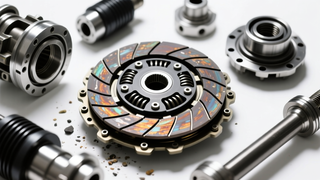
The drivetrain friction clutch is subjected to immense thermal and mechanical stress. Identifying wear before catastrophic failure (such as friction disc disintegration or flywheel scoring) requires attention to specific operational symptoms.
Slipping Under Load and Torque Capacity Loss
Clutch slip is the most common indicator of friction material degradation. In a properly functioning assembly, the pressure plate clamp load (often exceeding 3,200 lbs on heavy-duty aftermarket setups like the South Bend DD3250-6) locks the friction disc to the flywheel. When the friction material wears thin, the diaphragm spring over-centers, losing its mechanical advantage and reducing clamp load. Symptoms manifest as RPM flaring without a corresponding increase in vehicle speed, typically occurring in higher gears (5th or 6th) under heavy throttle application or while towing on an incline. If a Cummins G56 transmission exhibits slip at 2,800 RPM under a 15,000 lb towing load, the friction coefficient has critically degraded.
Chatter, Harmonic Resonance, and Flywheel Degradation
Clutch chatter during engagement is rarely an issue with the friction disc itself; it is typically a symptom of flywheel runout, damaged torsional dampening springs, or a failing Dual-Mass Flywheel (DMF). On Ford ZF S6-650 applications, the DMF utilizes internal grease and arc springs to absorb diesel torsional vibrations. When these springs fatigue or the internal grease burns off due to excessive slip-heat, the flywheel develops severe harmonic resonance. This translates into a violent shudder upon pedal release. Measuring flywheel runout with a dial indicator is mandatory; any reading exceeding 0.005 inches (0.127mm) dictates immediate flywheel replacement or resurfacing, as it will destroy a new clutch disc within 5,000 miles.
Pedal Engagement and Hydraulic Free-Play Deviations
Modern heavy-duty manual transmissions utilize hydraulic clutch actuation. A healthy system requires 0.5 to 0.75 inches of free-play at the master cylinder pushrod before engaging the release bearing. If the engagement point creeps to the very top of the pedal travel, it indicates severe friction disc wear or a worn pivot ball and throwout bearing assembly. Conversely, a spongy pedal or failure to disengage fully points to hydraulic degradation (e.g., a failing slave cylinder or contaminated DOT 3/4 fluid boiling under transmission tunnel heat) rather than mechanical clutch wear.
Lifespan Indicators: Teardown Measurements and Limits
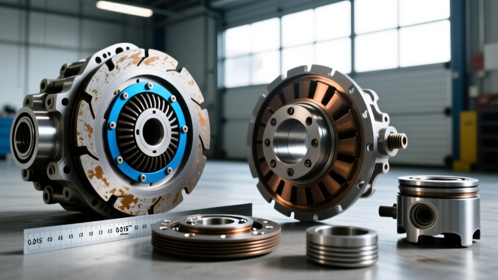
Once the transmission is removed, visual inspection is insufficient. Precision measurement tools are required to determine if components are within service limits. The following table outlines critical specifications for common heavy-duty and performance manual transmissions.
| Transmission Model | Clutch Assembly (Example) | New Friction Thickness | Wear Limit (Rivet Clearance) | Max Flywheel Runout |
|---|---|---|---|---|
| Aisin G56 (Dodge 5.9/6.7L) | South Bend DD3250-6 | 0.315' (8.0mm) | 0.216' (5.5mm) | 0.006' (0.15mm) |
| ZF S6-650 (Ford 7.3L/6.0L) | LUK RepSet Pro DMF | 0.305' (7.7mm) | 0.196' (5.0mm) | 0.005' (0.12mm) |
| Tremec T56 Magnum | McLeod RXT Twin Disc | 0.250' (6.3mm) per disc | 0.180' (4.5mm) per disc | 0.004' (0.10mm) |
When measuring friction disc thickness, technicians must use a digital caliper measuring from the friction surface to the rivet heads. If the distance from the friction material surface to the rivet is less than 0.030 inches, the disc is at imminent risk of scoring the flywheel and pressure plate. Additionally, inspect the input shaft splines for 'stepping' or galling, which prevents the disc from floating freely and causes dragging or premature wear.
Fan Clutch Removal: Diagnostics and Extraction Protocols
While the drivetrain clutch handles torque transfer, the engine fan clutch manages thermal dissipation. During an engine-out service or cooling system overhaul, fan clutch removal is a necessary step that requires specific diagnostic and extraction protocols.
Viscous Shear Testing and Mechanical Extraction
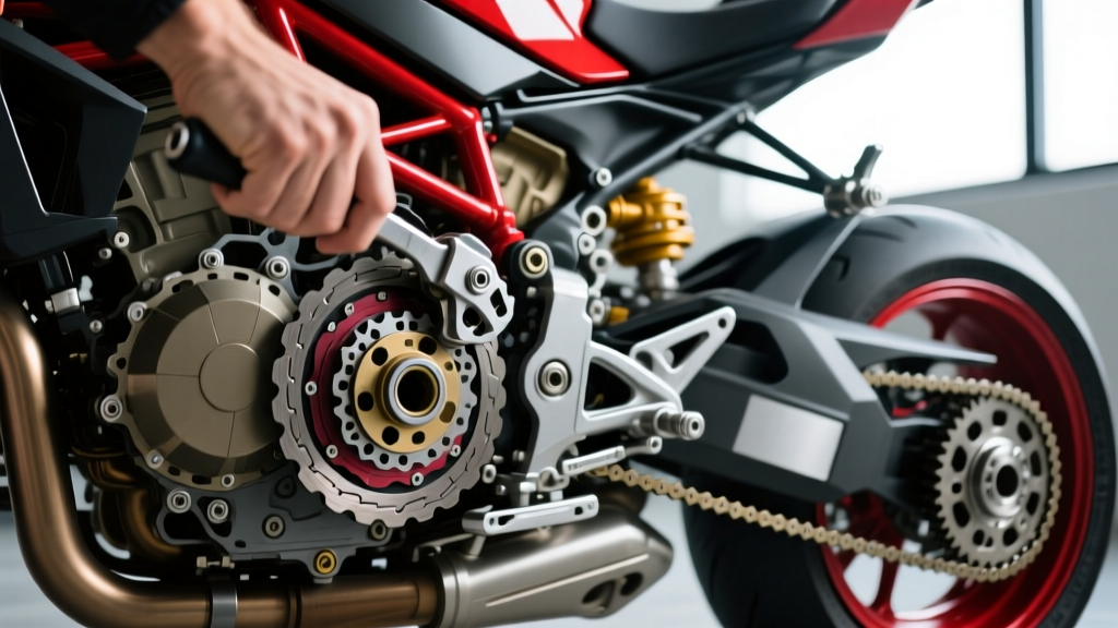
On the 6.7L Cummins ISB engine, the fan clutch is a thermostatically controlled viscous drive unit. Before removal, a cold spin-test should reveal moderate resistance, while a hot engine (post-towing) should lock the clutch, producing a distinct 'roar' and high CFM airflow. If the fan spins freely with zero resistance when hot, the internal silicone shear fluid has leaked, necessitating replacement. Extraction of the Cummins fan clutch requires navigating a massive M36 x 1.5 left-hand thread. Technicians must use a specialized fan clutch wrench set (such as OTC 4321 or Cummins tool 3161168) and a long breaker bar anchored against the water pump pulley bolts. Applying heat to the hub with an induction heater is often required if the unit has suffered from years of thermal cycling and galvanic corrosion.
Electronic Fan Clutch PWM Diagnostics
Ford's 6.0L and 6.4L Powerstroke engines utilize an electronically controlled viscous fan clutch. Rather than a bimetallic strip, the Powertrain Control Module (PCM) sends a Pulse Width Modulated (PWM) signal to an electromagnetic coil inside the clutch hub, which opens a valve to allow silicone fluid into the shear cavity. Before removing the unit, technicians should back-probe the connector to verify the 12V power supply and the PWM ground signal. If the PCM commands a 70% duty cycle but the fan remains disengaged, the internal electromagnetic coil has failed (often drawing an open circuit or shorting out). Removal on these platforms typically involves a standard right-hand thread but requires extreme care to avoid damaging the delicate wiring harness routed through the fan shroud.
Reassembly Best Practices and Torque Specifications
Whether reinstalling a Tremec T56 Magnum or an Aisin G56, reassembly demands strict adherence to torque specifications and alignment procedures. The bellhousing-to-engine block dowel pins must be checked for runout; if runout exceeds 0.005 inches, offset dowel pins must be installed to prevent input shaft binding and premature pilot bearing failure. Flywheel bolts on a Cummins application require a torque sequence of 105 lb-ft, followed by a 125 lb-ft final pass, often secured with medium-strength threadlocker. For the cooling system, the fan clutch hub must be torqued to engine-specific specifications (e.g., 85 lb-ft for the Cummins M36 hub) to prevent catastrophic detachment at 3,000 RPM. By mastering both the drivetrain friction assembly and the thermal fan clutch removal processes, technicians ensure comprehensive powertrain reliability for the most demanding heavy-duty applications.
For further technical data on heavy-duty diesel components and tooling, fleet mechanics frequently consult resources like Geno's Garage for Cummins-specific service bulletins and extraction tooling guides.