Decoding the Harley Clutch Assembly Diagram
For new riders and amateur garage mechanics, staring at a Harley clutch assembly diagram can feel like reading an ancient map. However, understanding this diagram is the absolute first step in diagnosing why your motorcycle lurches when shifting into first gear, or why the engine revs freely on the highway without accelerating. Unlike the dry clutches found on many European bikes or the complex torque converters in automotive automatic transmissions (like the ZF 8HP), Harley-Davidson Big Twins and Sportsters utilize a wet, multi-plate clutch system bathed in primary chaincase fluid.
Whether you are riding a legacy Twin Cam or a modern Milwaukee-Eight (M8), the fundamental physics of clutch engagement and disengagement remain the same. By breaking down the assembly diagram into its core functional zones, we can systematically isolate engagement failures, dragging issues, and catastrophic slippage.
The Friction Zone: Basket, Hub, and Plates
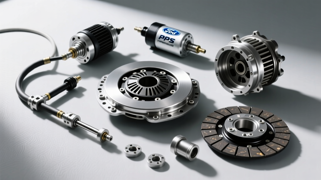
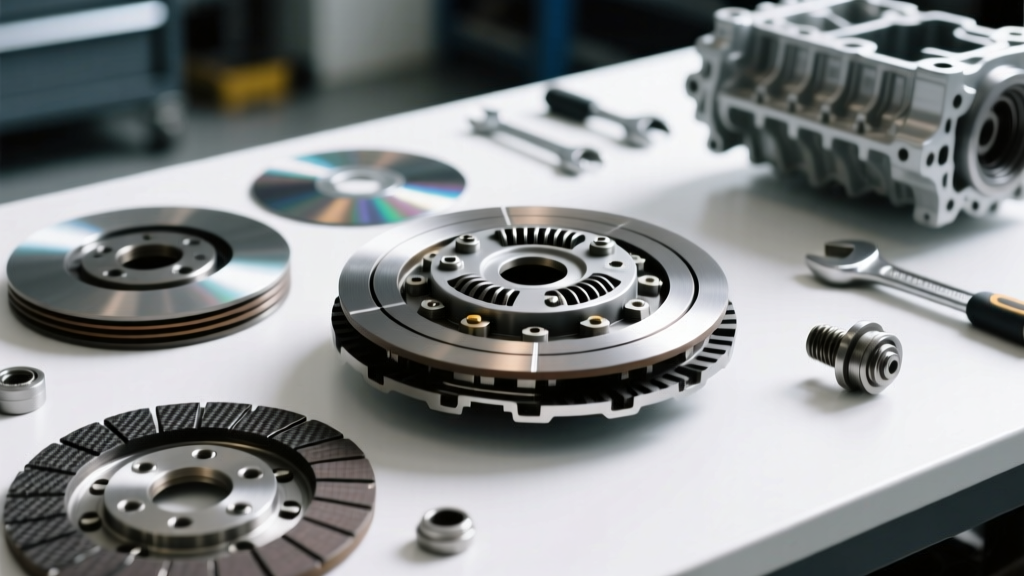
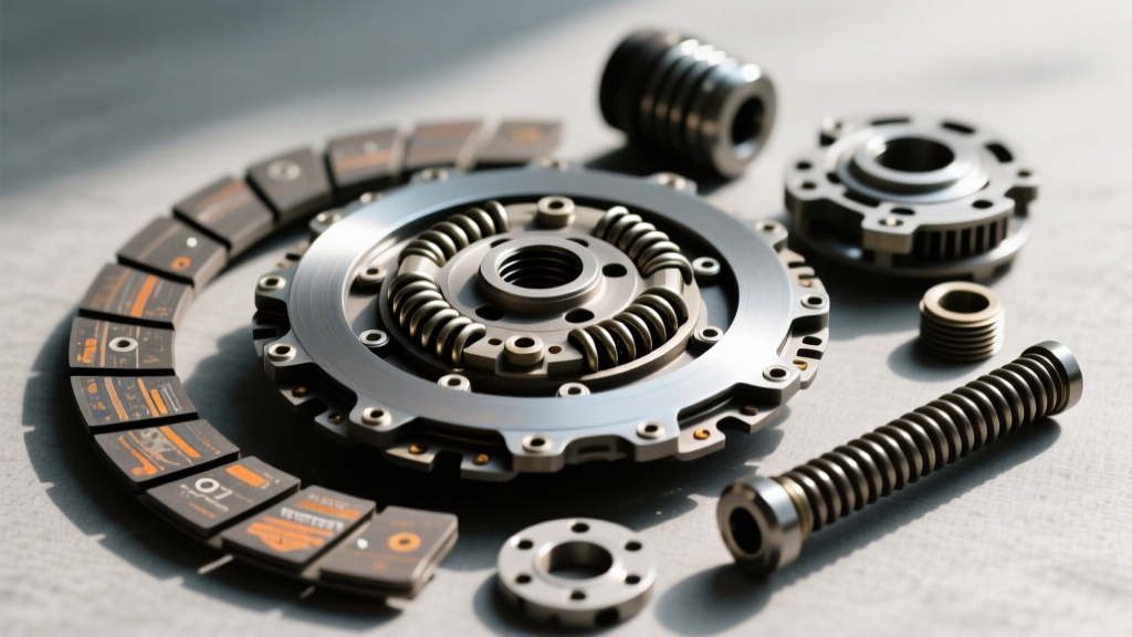
Looking at the outer section of your assembly diagram, you will see the clutch basket (outer hub) and the clutch hub (inner hub). The basket is driven by the primary chain, while the hub is splined directly to the transmission mainshaft. Alternating between these two components are the friction plates (which spline to the basket) and steel separator plates (which spline to the hub). When the diaphragm spring applies clamping force, friction locks the basket and hub together, engaging the drivetrain.
The Actuation System: Pushrod and Diaphragm
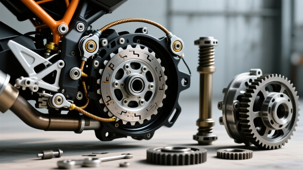
The inner section of the diagram reveals the release mechanism. When you pull the clutch lever, a cable or hydraulic actuator pushes a release bearing against the diaphragm spring (or coil springs on pre-2017 models). This spring pressure lifts the pressure plate, separating the friction and steel plates, thereby disengaging the clutch to allow for gear changes.
Diagnosing Disengagement Failures (Clutch Drag)
If your motorcycle creeps forward with the clutch lever fully pulled in, or if it violently lurches and stalls when shifting into first gear from a stop, your clutch is failing to disengage. This is commonly known as "clutch drag." Based on the assembly diagram, here are the primary mechanical culprits:
- Notched Basket Fingers: Over thousands of miles, the tangs of the friction plates hammer into the aluminum fingers of the clutch basket, creating deep grooves or "notches." When you pull the lever, the plates physically hang up in these grooves and refuse to separate. Fix: Inspect the basket with a fingernail; if it catches, the basket must be replaced or fitted with a steel-lined aftermarket insert.
- Warped Steel Plates: Aggressive riding or "popping" the clutch can overheat the steel separator plates, causing them to warp like a potato chip. Even when clamping pressure is removed, their wavy shape keeps them in contact with the friction plates. Fix: Check flatness on a glass surface with a feeler gauge. Maximum allowable warp is typically 0.005 inches.
- Pushrod Adjustment Errors: If the central pushrod is adjusted too loosely, the release bearing cannot travel far enough to fully compress the diaphragm spring, resulting in incomplete disengagement.
Diagnosing Engagement Failures (Clutch Slip)
Clutch slippage occurs when the lever is fully released, but the engine RPMs climb without a proportional increase in wheel speed. This means the clamping force is insufficient to overcome the engine's torque output.
The Assist & Slip (A&S) Ramp Mechanism
If you are reviewing a Harley clutch assembly diagram for a 2017 or newer Milwaukee-Eight model, you will notice the Assist & Slip (A&S) clutch mechanism. This system uses a specialized ramp and cam design to multiply clamping force under heavy acceleration while reducing lever effort. However, if the A&S ramps become contaminated with metallic debris from a failing primary chain tensioner, the mechanism will bind, leading to severe slippage and erratic engagement.
Fluid Contamination and Friction Modifiers
The most common cause of sudden clutch slip is the wrong primary fluid. Harley wet clutches require fluid with specific friction coefficients. Using automotive motor oils that contain "friction modifiers" (often labeled as "Energy Conserving" on the API donut) will coat the friction plates in a slick layer of molybdenum, destroying engagement. Always use fluids specifically formulated for wet clutches, such as Harley-Davidson Genuine Syn3 or Formula+.
Critical Measurements and Torque Specifications
When tearing down the clutch pack based on your diagram, precision is mandatory. Guesswork leads to premature failure. Use the following benchmark specifications for standard Big Twin applications:
| Component / Specification | Measurement / Value | Service Limit / Notes |
|---|---|---|
| Friction Plate Thickness (New) | 0.120" - 0.125" | Replace entire pack if any plate measures below 0.090" |
| Steel Plate Flatness | Perfectly Flat | Max warp: 0.005" (Check on tempered glass) |
| Clutch Hub Nut Torque | 70 - 80 ft-lbs | MUST use Red Loctite 271 (High Strength) |
| Diaphragm Spring Free Length | Varies by OEM vs. Aftermarket | Replace if heat-blued or sagging >10% of spec |
| Primary Chaincase Capacity | 32 oz (1 Quart) | Fill to the bottom of the clutch basket inspection hole |
The 3-Point Clutch Adjustment Procedure
Before ordering new parts, ensure your engagement issues aren't simply the result of cable stretch or thermal expansion. A proper adjustment follows a strict three-point sequence to ensure the pushrod perfectly interfaces with the release bearing shown in your assembly diagram.
- Cable Slack Adjustment: Back off the cable adjuster at the handlebar and the lower housing until the clutch lever has maximum free play. You want the cable completely slack for the next steps.
- Pushrod / Screw Adjustment: Remove the derby cover. Loosen the locknut on the central clutch adjustment screw. Turn the screw inward (clockwise) until you feel firm resistance—this is the pushrod contacting the release bearing. Back the screw out exactly 1/2 to 3/4 of a turn, then hold the screw perfectly still while tightening the locknut to 72-120 in-lbs.
- Final Cable Tension: Re-tighten the cable adjusters until you achieve exactly 1/16" to 1/8" of free play at the clutch lever perch. This tiny gap is critical; without it, the cable will pull the pushrod constantly, riding the release bearing and causing severe slippage and bearing failure.
Rebuild Costs and Component Upgrades for 2026
If your measurements confirm the friction material is worn or the steels are warped, a rebuild is necessary. As of 2026, riders have several distinct paths depending on their torque output and budget.
- OEM Replacement Pack ($140 - $180): Best for stock or mildly modified touring bikes. Provides smooth, predictable engagement and quiet operation.
- Barnett Kevlar / Carbon Fiber Kits ($190 - $250): Highly recommended for Stage 2 or Stage 3 builds producing over 100 lb-ft of torque. Kevlar faces offer a slightly more aggressive "grab" but resist fading under extreme heat. You can source direct-fit kits from Barnett Clutches using specific application guides (e.g., part number 307-30-1005 for standard Twin Cam applications).
- Hydraulic Actuator Upgrades ($350 - $500): Many riders experiencing chronic cable-stretch disengagement issues are retrofitting hydraulic slave cylinders (like the Screamin' Eagle or Speed's Performance kits). Hydraulics self-compensate for friction plate wear, maintaining a consistent engagement point at the lever over thousands of miles.
Expert Drivetrain Tip: Never soak modern Kevlar or Carbon-Kevlar friction plates in primary fluid overnight before installation. Unlike old cork or paper-based plates, modern synthetic materials are designed to be installed dry. Soaking them can cause the binding resins to break down prematurely, leading to early engagement slippage. Always defer to the manufacturer's specific insert instructions.
By treating the Harley clutch assembly diagram not just as a parts list, but as a functional map of hydraulic and mechanical forces, you can accurately diagnose engagement anomalies, perform precision adjustments, and keep your power reliably transferring to the rear wheel.