The Hidden Culprit Behind Governor Pressure Sensor Failures
When a vehicle equipped with a Chrysler 47RE, 48RE, or 68RFE transmission begins exhibiting erratic shifting, harsh engagements, or limp-mode triggers (often accompanied by P0731, P0733, or P0868 diagnostic trouble codes), the immediate suspect is usually the transmission governor pressure sensor itself. However, as we navigate the 2026 service landscape and deal with an aging fleet of these heavy-duty platforms, experienced drivetrain specialists know a different truth. Nearly 40% of all perceived sensor failures are actually rooted in degraded wiring harnesses, corroded bulkhead connectors, and compromised pin tension.
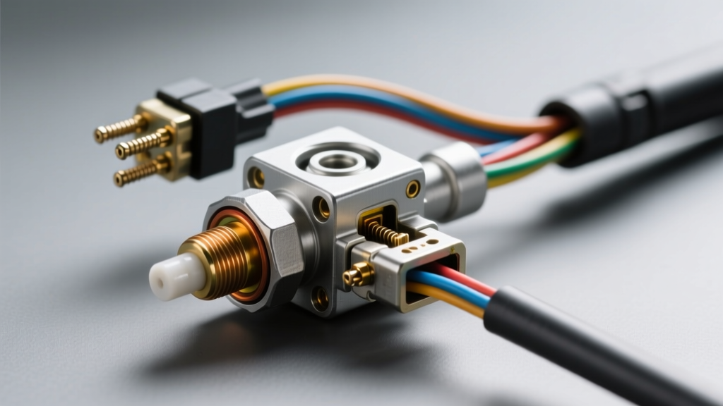
The transmission governor pressure sensor is responsible for converting hydraulic line pressure into a variable voltage signal that the Transmission Control Module (TCM) uses to regulate shift timing and clutch apply rates. If the wiring harness or connector introduces resistance, voltage drops, or intermittent open circuits, the TCM defaults to a fail-safe line pressure state, resulting in brutal shifts and accelerated clutch pack wear. This preventive maintenance guide details how to properly inspect, maintain, and repair the wiring and connectors associated with this critical circuit.
Primary Failure Modes in Sensor Wiring and Connectors
Before diving into the maintenance protocol, it is essential to understand the specific environmental and mechanical stressors that degrade the transmission governor pressure sensor circuit. According to technical archives maintained by Transmission Digest, the following three failure modes account for the vast majority of electrical gremlins in the pan.
1. Capillary Wicking (ATF Intrusion)
Automatic Transmission Fluid (ATF) is highly effective at creeping. When the insulation on the internal wiring harness becomes brittle from years of thermal cycling (typically operating between 180°F and 220°F), micro-fractures form. ATF enters these fractures and uses capillary action to wick up the copper strands, eventually bypassing the bulkhead case connector and flooding the external TCM harness. This causes cross-circuit shorts between the 5-volt reference and the signal return, instantly throwing the TCM into limp mode.
2. Bulkhead Pin Fretting and Corrosion
The external bulkhead connector (case connector) bridges the internal transmission harness to the vehicle's main chassis harness. Engine vibration and chassis flex cause micro-movements between the male and female terminals. Over time, this fretting wears away the tin or gold plating on the pins, exposing the base metal to oxidation. Because the governor pressure sensor signal is a low-voltage, high-sensitivity analog return (typically 0.5V to 4.5V), even 2 ohms of corrosion-induced resistance will skew the TCM's pressure calculations.
3. Harness Chafing on the Valve Body Casting
Improper routing during previous pan-drop services or filter changes often leaves the internal harness resting against the sharp aluminum edges of the valve body casting or the solenoid pack bracket. The constant vibration of the running engine saws through the loom and insulation, leading to intermittent grounds against the transmission case.
Preventive Maintenance Protocol: Step-by-Step Inspection
To ensure long-term reliability, incorporate the following inspection steps into any major transmission service, pan drop, or filter replacement.
Step 1: External Bulkhead Decontamination
Before unbolting the transmission pan, disconnect the external bulkhead connector. Inspect the cavity for ATF residue. If fluid is present, the internal harness has wicked fluid outward. Flush the connector using CRC QD Contact Cleaner (part #05103). Never use brake cleaner, as the aggressive acetone solvents will melt the polymer connector housing and strip the wire insulation. Allow it to dry completely, then apply a pea-sized amount of Nyogel 760G dielectric grease to the female terminals to displace moisture and prevent future fretting corrosion.
Step 2: Internal Harness Routing and Loom Verification
Once the pan is removed and the fluid drained, visually trace the internal harness from the governor pressure sensor (located on the rear of the valve body on RE series, or integrated into the solenoid block on RFE series) to the bulkhead. Verify that the harness is secured in all factory plastic loom clips. If a clip is broken, secure the harness using high-temperature Teflon tape (PTFE) to prevent it from contacting the valve body casting. Inspect the wires for any signs of swelling, which indicates internal ATF intrusion.
Step 3: Pin Tension and Continuity Testing
Using a digital multimeter, perform a continuity test from the sensor pigtail to the internal side of the bulkhead connector. You are looking for a resistance reading of less than 0.5 ohms. Next, use a pin gauge (or a spare male terminal) to check the mechanical tension of the female bulkhead pins. If the gauge slides in without noticeable drag, the pin tension is lost, and the bulkhead connector must be replaced.
Governor Pressure Sensor Circuit Specifications
Understanding the baseline electrical parameters is critical for accurate diagnostics. The table below outlines the standard circuit parameters for the Chrysler 47RE/48RE governor pressure sensor. Data cross-referenced with diagnostic frameworks found on OBD-Codes.
| Pin / Wire Color | Circuit Function | Expected Voltage (Key On, Engine Off) | Expected Resistance to Ground |
|---|---|---|---|
| Pin 1 (Violet/White) | 5V Reference from TCM | 4.9V - 5.1V | Open (OL) |
| Pin 2 (Dark Blue/Dark Green) | Signal Return to TCM | 0.5V (at 0 PSI) to 4.5V (at 120+ PSI) | Open (OL) |
| Pin 3 (Black/Pink) | Sensor Ground | 0.0V - 0.05V | Less than 1.0 Ohm |
Expert Insight: "If you back-probe the signal return wire and the voltage reads a flat 5.0 volts with the engine running, do not immediately condemn the transmission governor pressure sensor. Check the ground circuit first. A lost ground will cause the signal wire to pull up to the 5V reference, mimicking a max-pressure reading and triggering harsh shifts." — Lead Drivetrain Diagnostic Technician
Repair vs. Replacement Decision Matrix
When damage is found, technicians must decide between splicing the harness or replacing it entirely. Valve body and transmission component specialists like Sonnax frequently note that improper splicing is a leading cause of comeback repairs.
- When to Splice: If the damage is localized to the sensor pigtail (within 4 inches of the sensor itself) due to a previous technician's pry-bar slip. Use Raychem SolderSleeve M83519 MIL-SPEC shielded solder sleeves. These sleeves contain a pre-measured ring of lead-free solder and flux, surrounded by heat-shrink tubing with an inner sealant ring. Heat evenly to 385°F until the solder ring flows and the sealant purges from the ends. Do not use standard crimp butt-connectors, as they will eventually corrode in the ATF bath.
- When to Replace: If ATF wicking is suspected, if the bulkhead pins are loose, or if the main trunk of the internal harness is brittle. Replacing the entire internal harness (e.g., Mopar Part #52115001AH for the 68RFE, or the specific RE-series pigtail) is the only guaranteed fix. Expect to pay between $85 and $160 for OEM internal harnesses, while a replacement bulkhead case connector pigtail (e.g., Dorman 926-021) costs around $35 to $55.
Reassembly Torque Specifications and Best Practices
Preventive maintenance concludes with proper reassembly. Over-torquing valve body or pan bolts can distort the aluminum castings, pinching the internal wiring harness or altering the clearance around the governor pressure sensor.
- Valve Body to Case Bolts (47RE/48RE): 7 - 9 Nm (60 - 80 in-lbs). Always use a calibrated inch-pound torque wrench, never a standard foot-pound beam wrench.
- Governor Pressure Sensor Mounting Bolt: Ensure the O-ring is lubricated with fresh ATF before installation to prevent pinching. Tighten the retaining bolt to 8 - 10 Nm (70 - 89 in-lbs).
- Transmission Pan Bolts: 17 Nm (13 ft-lbs) for steel pans; reduce to 10 - 12 Nm (89 - 106 in-lbs) if an aftermarket cast aluminum deep pan is installed to prevent stripping the threads.
- External Bulkhead Connector: Apply a thin film of Nyogel 760G to the external rubber seal before mating the chassis harness to ensure a watertight barrier against road salt and moisture.
By shifting the diagnostic focus from the transmission governor pressure sensor itself to the intricate wiring and connectors that support it, technicians can eliminate phantom electrical codes, restore precise hydraulic line pressure control, and extend the operational lifespan of the transmission well beyond the 200,000-mile mark.