The Complexity of GM Manual Truck Drivetrains
When diagnosing clutch pedal problems on GM full-size trucks (GMT800 and GMT900 Silverado and Sierra 1500 platforms) equipped with the 5.3L Vortec V8 and manual transmissions like the NV3500 or Tremec T56, mechanics face a unique intersection of hydraulic and mechanical failures. A spongy, hard, or vibrating clutch pedal is rarely just a 'bad clutch.' It is often a cascading failure involving the hydraulic master cylinder, the Clutch Delay Valve (CDV), the concentric slave cylinder, or the engine's rotating assembly. Furthermore, performing the necessary transmission teardown on these longitudinal V8 platforms requires specialized front-end disassembly, making tools like a heavy-duty fan clutch holder an absolute necessity for bellhousing access.
This model-specific repair guide details the exact diagnostic frameworks, teardown procedures, and hydraulic restoration steps required to cure clutch pedal anomalies on GM's iconic V8 trucks.
Decoding Clutch Pedal Symptoms
Before unbolting a single bellhousing bolt, you must accurately map the pedal symptom to its physical root cause. The GM truck hydraulic clutch system operates at high pressure, and fluid degradation or mechanical binding will manifest in three distinct ways at the driver's foot.
1. The Spongy or Soft Pedal
A soft pedal that sinks to the floor or fails to return crisply is almost exclusively a hydraulic issue. On GM trucks, this is typically caused by three factors:
- Hygroscopic Fluid Degradation: DOT 3 and DOT 4 fluids absorb moisture. Over time, this lowers the boiling point and introduces compressible vapor pockets into the Tremec or NV3500 hydraulic lines.
- Master Cylinder Bypass: The internal seals of the FTE or GM OEM master cylinder wear out, allowing fluid to bypass the piston under load rather than pushing the slave cylinder.
- The Clutch Delay Valve (CDV): GM installed a CDV (a restrictor plate with a tiny 1.5mm orifice) in the hard line between the master and slave cylinders to prevent drivetrain shock during aggressive shifts. By 2026, it is widely recognized that the CDV causes a spongy pedal feel, traps air in the line, and accelerates slave cylinder wear. Deleting the CDV is a mandatory step in any modern GM truck clutch repair.
2. The Hard or Binding Pedal
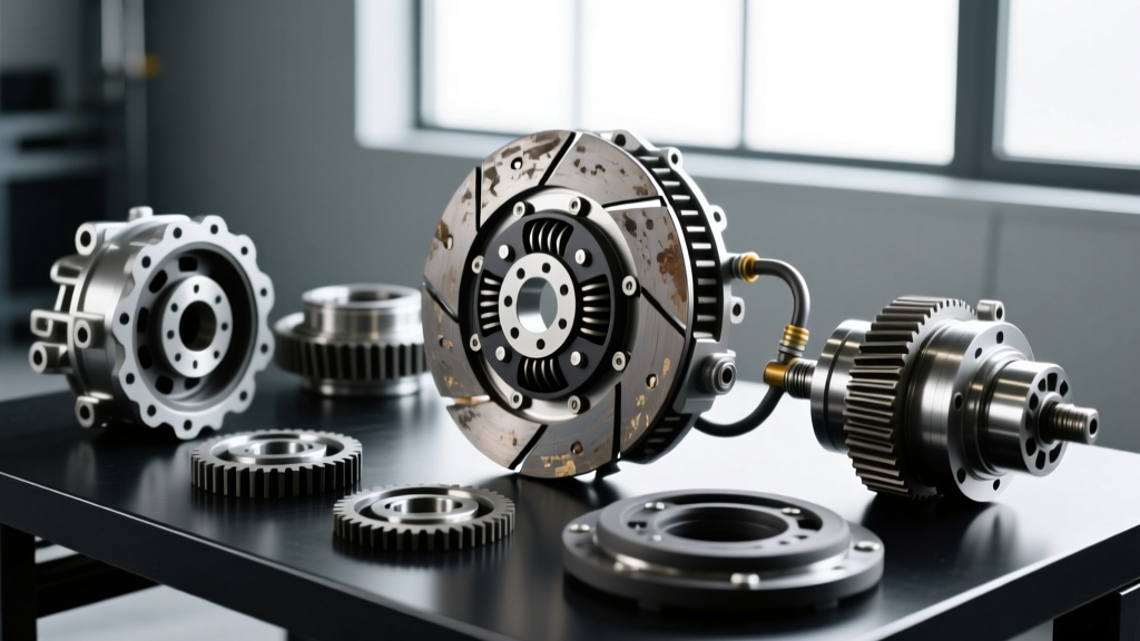
If the pedal requires excessive physical force to depress, the issue is mechanical binding. Check the firewall-mounted pedal pivot ball for severe corrosion or lack of lubrication. If the pivot is clean, the fault lies inside the bellhousing. The diaphragm fingers on the pressure plate may be fatigued and binding against the throwout bearing, or the clutch disc hub splines are rusted and binding on the transmission input shaft. In high-mileage 5.3L trucks, a failing pilot bearing can also cause the input shaft to bind, transmitting a harsh, stiff feel directly to the pedal.
3. The Vibrating Pedal
Pedal vibration (often described as a 'chatter' felt through the foot during engagement) points to rotational imbalance or harmonic resonance. This is usually caused by a warped dual-mass or single-mass flywheel, broken torsional damper springs inside the clutch disc, or oil contamination on the friction material from a leaking rear main seal. On GM LS-based Vortec engines, a worn needle-style pilot bearing will allow the input shaft to wobble, creating a high-frequency vibration that travels through the hydraulic column to the pedal.
Teardown Phase: Clearing the Viscous Fan Clutch
To properly service the clutch hydraulics, replace the flywheel, or swap the transmission on a GMT800/900 5.3L truck, you must create clearance between the engine block and the radiator support. This requires removing the mechanical cooling fan. Because the fan is mounted to the water pump pulley via a large viscous fan clutch, removal presents a significant mechanical hurdle.
The fan clutch nut is a massive 32mm or 36mm fitting with a left-hand thread. Because the water pump pulley spins freely on its bearings, applying a standard wrench will simply rotate the pulley. You must use a dedicated fan clutch holder tool (such as the Lisle 39250 or OTC equivalent) to lock the pulley in place.
Step-by-Step Fan Clutch Removal
- Leave the serpentine belt installed to provide initial tension on the pulley system.
- Position the fan clutch holder tool so its pins slot perfectly into the holes on the water pump pulley face.
- Apply counter-clockwise force to the holder to prevent rotation.
- Use a 32mm/36mm open-end wrench or a specialized fan clutch wrench to break the left-hand nut loose. Note: An air hammer with a blunt chisel attachment struck against the wrench tang is a common shop trick if the nut is seized from years of heat cycling.
- Once broken loose, remove the nut, detach the fan shroud, and pull the radiator to expose the lower bellhousing bolts and transmission crossmember.
Expert Warning: Never attempt to hold the water pump pulley by wedging a screwdriver into the belt ribs. This will destroy the serpentine belt and score the pulley grooves, leading to immediate accessory drive failure upon reassembly.
GM Truck Drivetrain & Hydraulic Specifications
Precision repairs require exact data. Below are the critical specifications for the 5.3L Vortec manual truck platform.
| Component / Specification | Part Number / Value | Notes |
|---|---|---|
| Master Cylinder (OEM Replacement) | GM 19207651 / FTE KG14012.1.1 | Inspect firewall pushrod pin for wear |
| Concentric Slave Cylinder (CSC) | Sachs SH5005 / GM 12583638 | Must be pre-filled before installation |
| CDV Delete Union Fitting | GM 12383671 | Replaces the restricted hard-line union |
| Hydraulic Fluid Capacity | ~250 ml | Use fresh DOT 4 (e.g., ACDelco 88862806) |
| Flywheel to Crank Torque (M11) | 74 lb-ft + 90 degrees | TTY bolts; MUST be replaced if removed |
| Bellhousing to Block Torque (M12) | 74 lb-ft | Use threadlocker on top bolts |
Hydraulic Restoration and the CDV Delete
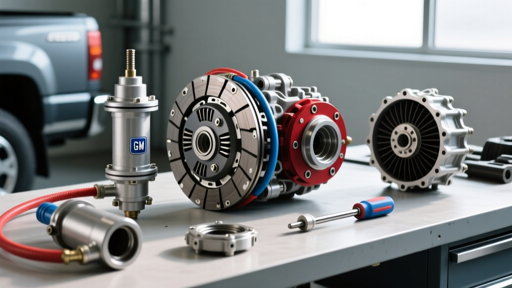
Once the Tremec or NV3500 transmission is out and the old slave cylinder is removed, the hydraulic system must be overhauled. The factory slave cylinder is known to weep fluid into the bellhousing, contaminating the clutch disc. Always replace the slave cylinder and the master cylinder as a matched set if the truck has over 80,000 miles.
Executing the CDV Delete
Locate the hard hydraulic line running from the master cylinder down to the bellhousing. Midway along the frame rail, you will find a union fitting housing the Clutch Delay Valve. Unbolt this fitting, discard the restrictor plate, and install the standard GM union fitting (Part #12383671). This restores full, unrestricted fluid volume to the slave cylinder, resulting in a firm, predictable pedal feel and significantly faster clutch engagement.
Pressure Bleeding the System
Gravity bleeding is insufficient for the GM truck hydraulic layout due to the upward routing of the line into the bellhousing. You must use a pressure bleeder (like a Motive Products Power Bleeder) set to exactly 12 to 15 PSI. Exceeding 20 PSI can rupture the internal diaphragm of the new concentric slave cylinder. Open the bleeder valve located on the side of the slave cylinder (accessible through the bellhousing inspection cover or via a remote tube routed outside the bellhousing during assembly) until a steady stream of bubble-free DOT 4 fluid emerges.
Reassembly and Final Diagnostics
When reinstalling the Tremec T56 or NV3500, ensure the clutch disc is perfectly aligned using a spline tool. A misaligned disc will prevent the transmission from mating to the block and will bend the clutch fingers, resulting in an immediately hard pedal. Torque the bellhousing to the 5.3L block using the sequence outlined in the Tremec service documentation, ensuring the dowel pins are fully seated to prevent input shaft misalignment and subsequent pilot bearing failure.
Reinstall the radiator, shrouds, and water pump pulley. Thread the viscous fan clutch nut back onto the water pump shaft (remember: left-hand thread) and torque to factory specifications. Once the drivetrain is fully assembled and the hydraulic system is bled, pump the clutch pedal 20 times with the engine off to seat the slave cylinder piston against the pressure plate fingers. Start the engine, verify the pedal returns crisply, and test for gear engagement in Reverse and First. If the pedal remains firm and chatter-free, the diagnostic and repair protocol is complete.