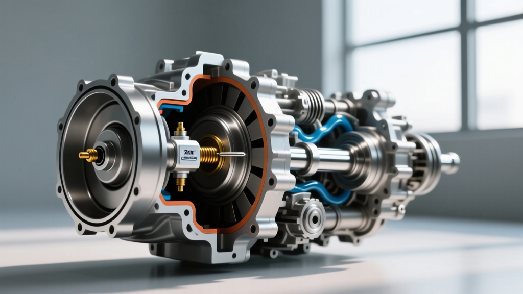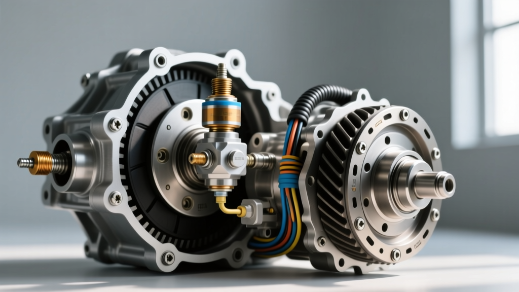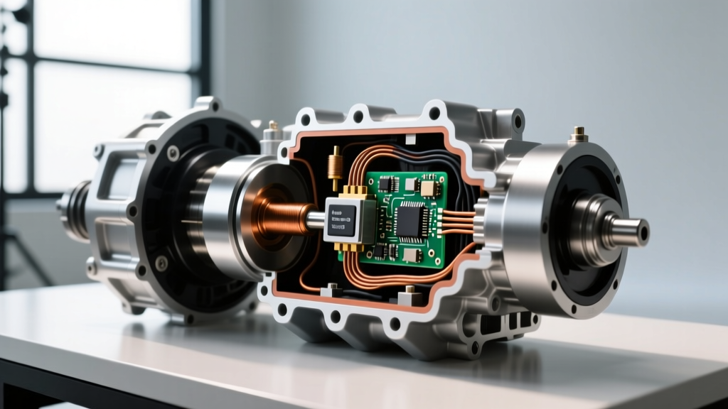
Real-World Diagnostic Scenario: A 2016 Chevrolet Silverado equipped with the 6L80 transmission arrives in the shop in limp mode. The scan tool reveals two seemingly unrelated codes: P0720 (Output Speed Sensor Circuit) and P0711 (Transmission Temp Sensor Range/Performance). Why would a speed sensor and a temperature thermistor fail simultaneously? The answer lies in the integrated internal wiring harness architecture and shared reference circuits.
The Telemetry Symbiosis: Why Speed and Temperature Share a Circuit
In modern powertrain control systems, the Transmission Control Module (TCM) relies on a continuous stream of telemetry to calculate shift timing, torque converter clutch (TCC) apply rates, and line pressure. The transmission output speed sensor (OSS) and the transmission temp sensor (TFT) are two of the most critical inputs. While they measure entirely different physical properties—magnetic reluctor wheel rotation versus fluid thermal dynamics—they are frequently bundled together on the same Internal Wiring Harness (IWH) or Mechatronic sleeve.
When diagnosing a P0720 or P0722 code, amateur technicians often replace the OSS in isolation, only to find the code returns. This happens because the OSS and the transmission temp sensor often share a common 5-volt reference line or a shared signal return ground inside the TCM. A short to ground on the temperature thermistor circuit can pull down the 5V reference, causing the TCM to simultaneously lose the OSS signal, triggering a cascade of limp-mode fault codes.
Variable Reluctance vs. Hall-Effect Architectures
To diagnose these circuits accurately, you must first identify the sensor architecture utilized by your specific transmission:
- Variable Reluctance (VR) Sensors: Common in older and mid-generation transmissions like the GM 4L60E and early 6L80. A VR sensor is a passive magnetic pickup that generates an alternating current (AC) sine wave as the teeth of the reluctor ring pass by its magnetic core. The frequency and amplitude of the sine wave increase proportionally with output shaft RPM. At idle, you may see 0.5V AC; at highway speeds, this can exceed 40V AC before the TCM clamps the signal.
- Hall-Effect Sensors: Standard in modern units like the Ford 10R80 and GM 8L90. These are active, three-wire sensors requiring a 5V reference, a clean chassis ground, and a signal return wire. As the reluctor target passes, the internal transistor switches the signal wire between 0V and 5V, creating a crisp digital square wave. The TCM reads the frequency of the square wave, not the amplitude.
Integrated Internal Wiring Harnesses (IWHS): The GM 6L80/8L90 Paradigm
General Motors revolutionized (and complicated) internal transmission diagnostics with the 6L80 and 8L90 platforms. Instead of running individual wires through the transmission case bulkhead connector, GM utilizes a TEHCM (Transmission Electronics and Hydraulic Control Module) or an internal wiring harness that houses the Input Speed Sensor (ISS), Output Speed Sensor (OSS), and the transmission temp sensor in a single molded assembly.
The OEM replacement part for the GM 6L80 internal harness is typically ACDelco 24253109. Because the OSS and the transmission temp sensor share the same molded plastic loom, they are subjected to the same thermal cycling and fluid immersion. Over time, the Teflon-insulated wires become brittle. The most common failure point is where the harness wraps tightly around the valve body casting near the manual detent lever. Micro-fractures in the wire insulation allow conductive transmission fluid to bridge the OSS signal wire and the TFT ground wire, resulting in the dreaded P0720/P0711 combo.
Sensor Specifications by Transmission Model
| Transmission | Sensor Type | Resistance / Spec | Torque Spec | OEM Part Number |
|---|---|---|---|---|
| GM 6L80 | VR (Integrated Harness) | 800 - 1200 Ω | 11 Nm (97 lb-in) | ACDelco 24253109 |
| Ford 10R80 | Hall-Effect OSS | 5V Ref / Digital Square | 10 Nm (89 lb-in) | Ford FL3Z-7G101-A |
| ZF 8HP45/70 | Mechatronic Integrated | N/A (Internal PCB) | 10 Nm (Sleeve Bolts) | ZF 1087.298.325 |
Advanced Oscilloscope Diagnostics for the Output Speed Sensor
While a multimeter can verify continuity and basic resistance, an automotive oscilloscope is mandatory for definitive output speed sensor diagnostics. The TCM does not just look for the presence of a signal; it monitors the waveform's integrity to detect missing teeth or reluctor ring runout.
Reading the Waveform
Connect your oscilloscope leads to the OSS signal wire and a known good chassis ground. Backprobe the TCM connector or use a breakout box to avoid piercing the wire insulation, which can introduce fluid leaks into the harness.
- Healthy VR Signal: Should display a uniform, symmetrical sine wave. The peaks and valleys must be consistent. If the waveform shows 'shark-fin' distortion or flattened peaks, you likely have metallic debris clinging to the magnetic tip of the sensor, or excessive runout on the output shaft reluctor ring.
- Healthy Hall-Effect Signal: Should display a perfectly square 0V to 5V wave. The rise and fall times should be near-instantaneous. If the top of the square wave dips (e.g., only reaching 3.5V), you have excessive resistance in the 5V reference circuit or a failing pull-up resistor inside the TCM.
For deep technical insights on how mechanical wear affects sensor signals, the Sonnax ZF 8HP Tech Resource provides excellent documentation on how mechatronic sleeve wear in ZF 8-speed transmissions alters the air gap between the internal speed sensors and the reluctor targets, leading to intermittent signal dropouts at high fluid temperatures.
Step-by-Step Multimeter Pinout Testing
If you are dealing with a hard P0720 code and do not have a scope, follow this multimeter diagnostic tree at the TCM bulkhead connector (engine side):
- Verify the 5V Reference: With the key on, engine off (KOEO), backprobe the 5V reference pin. If it reads 0V, the TCM has likely shut down the reference circuit due to a short. Disconnect the internal transmission harness. If the 5V returns at the bulkhead, the short is inside the transmission (often a failed transmission temp sensor or chafed wire).
- Check the Shared Ground: Set your multimeter to Ohms. Measure the resistance between the sensor ground pin and the battery negative terminal. It should read less than 0.5 Ω. A reading of 2-5 Ω indicates a corroded ground splice inside the TEHCM.
- Measure OSS Resistance (VR Only): For the GM 6L80, measure across the ISS and OSS pins. A healthy VR sensor will read between 800 and 1200 Ω at room temperature. An open circuit (OL) confirms a broken wire inside the harness.
Real-World Failure Modes: The ZF 8HP Mechatronic
In ZF 8HP transmissions (found in BMW, Audi, Chrysler, and Ford applications), the output speed sensor is not a standalone component. It is soldered directly onto the printed circuit board inside the Mechatronic unit, reading through a plastic guide sleeve. Over time, the plastic sleeve degrades, and the bushing supporting the output shaft wears. This mechanical wear increases the air gap between the reluctor ring and the sensor. Because the sensor's magnetic field strength is fixed, the increased air gap results in a weaker signal that falls below the TCM's threshold at high RPMs, triggering a P0720 code only during aggressive highway driving. Replacing just the sleeve and mechatronic sealing kit often resolves the issue without replacing the entire $2,500 Mechatronic assembly.
Replacement Realities: Torque Specs, Fluids, and Costs
When replacing an integrated harness or standalone OSS, precision is critical. The TCM calculates slip ratios down to single-digit RPMs; a loose sensor will vibrate, altering the air gap and causing shift flares.
- GM 6L80/8L90 Harness Replacement: Requires dropping the transmission pan and removing the valve body/TEHCM. Torque spec: TEHCM to case bolts must be torqued to exactly 11 Nm (97 lb-in) in the specified spiral sequence. Over-torquing will crack the TEHCM housing. Expect to pay $180-$250 for the ACDelco OEM harness, with labor averaging 2.5 hours.
- Ford 10R80 OSS Replacement: Accessible via the pan. The sensor is held by a single 10mm bolt. Torque spec: 10 Nm (89 lb-in). Always replace the O-ring and lubricate it with fresh Mercon ULV fluid before installation. The stamped steel reluctor ring on the output shaft should be inspected for missing teeth or heavy clutch debris.
- Fluid Considerations: Whenever the pan is dropped for sensor diagnostics, the fluid and filter must be replaced. For the 6L80, this requires roughly 6-7 quarts of Dexron VI. For the ZF 8HP, you must use the specific ZF Lifeguard 8 fluid, as incorrect friction modifiers will cause immediate TCC shudder and corrupt the TCM's adaptive shift tables.
By understanding the shared electrical architecture between the transmission output speed sensor and the transmission temp sensor, technicians can move beyond guesswork, accurately diagnose complex P07xx fault codes, and avoid unnecessary part replacements.