The Shared 5-Volt Reference Nightmare on 6.7L Cummins Platforms
When a heavy-duty Ram truck equipped with a 6.7L Cummins engine and a 68RFE or Aisin AS69RC transmission rolls into the shop with a flashing gear indicator, limp mode, and a cluster of seemingly unrelated diagnostic trouble codes (DTCs), inexperienced technicians often start throwing parts at the vehicle. A classic and highly deceptive scenario involves the simultaneous triggering of P0720 (Output Speed Sensor Circuit Malfunction) alongside P2453 or P040D (EGR Sensor Circuit codes). To the untrained eye, these appear to be isolated failures. In reality, they are symptoms of a shared electrical architecture failing under the hood.
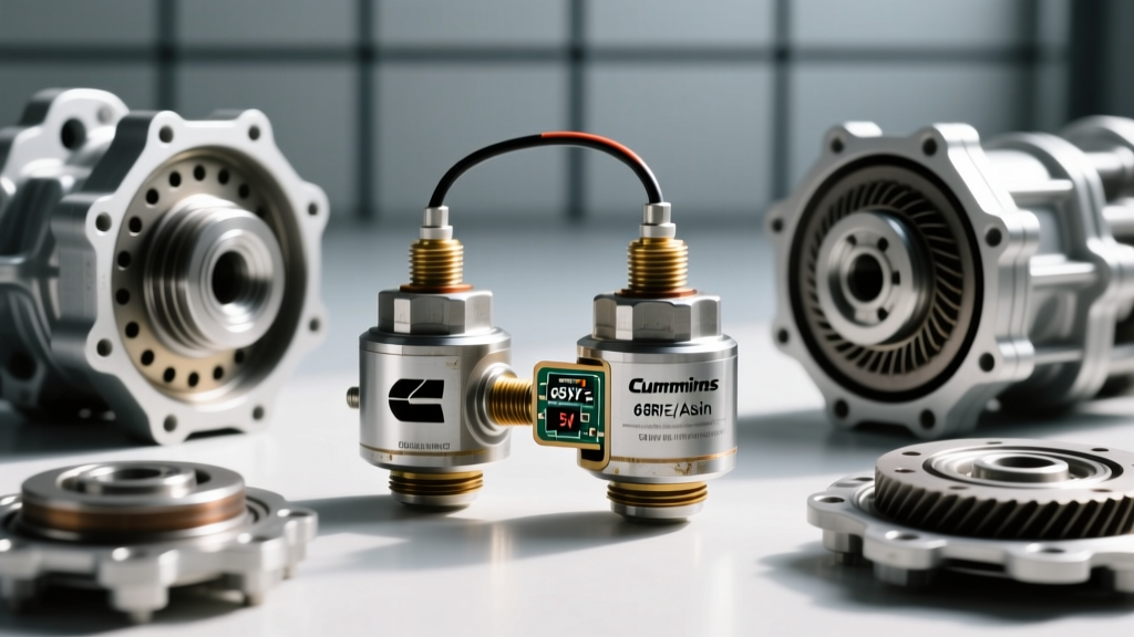
In modern heavy-duty powertrain management, the Engine Control Module (ECM) and Transmission Control Module (TCM) rely heavily on a shared 5-volt reference (5V Ref) bus to power critical analog and Hall-effect sensors. When an internal short or harness chafe occurs in the egr differential pressure sensor cummins circuit, it creates a 'pull-down' effect. This voltage drop starves the transmission output speed sensor of its required operating voltage, causing the TCM to incorrectly flag a transmission hard-part failure when the root cause is actually an engine emissions sensor shorting out the reference bus.
Understanding the Pull-Down Effect in CAN-Bus Architectures
The 5-volt reference circuit is a regulated DC voltage supply generated by the ECM's internal power management IC. It is designed to provide a stable 4.9V to 5.1V supply to multiple sensors, including the Manifold Absolute Pressure (MAP) sensor, Accelerator Pedal Position Sensor (APPS), the EGR differential pressure sensor, and in many Chrysler/Stellantis heavy-duty wiring architectures, the transmission speed sensors via a shared splice pack or common ground return.
If the internal silicon of the Cummins EGR DP sensor degrades due to extreme under-hood thermal cycling and soot ingress, it can develop a low-resistance path to ground. Because the 5V Ref circuit is wired in parallel, a short in the EGR sensor will pull the entire 5V bus down to 2.5V, 1.0V, or even 0V. The transmission output speed sensor (OSS), which requires a minimum of 4.5V to properly bias its internal Hall-effect or magneto-resistive circuitry, will output a clipped or completely flat signal. The TCM, seeing a 0 Hz frequency from the OSS while the input speed sensor (ISS) reads normal, immediately commands limp mode and sets P0720 to protect the planetary gearsets from catastrophic shift-timing errors.
Component Breakdown: EGR DP Sensor vs. Transmission OSS
To effectively diagnose this cross-system fault, technicians must understand the specific operational parameters and part numbers for both the engine and transmission components involved. Below is a technical comparison of the sensors commonly involved in this 5V Ref pull-down scenario on 2013–2024 Ram 2500/3500 platforms.
| Component | OEM Part Number | Signal Type | Typical Torque Spec | Est. Cost (2026) |
|---|---|---|---|---|
| Cummins EGR DP Sensor | 4921504 / 53033054AF | Analog 0.5V - 4.5V | Hand Tight + 1/4 Turn | $125 - $165 |
| 68RFE Output Speed Sensor | 05140900AB / 56028196AB | Hall-Effect Square Wave | 7 - 9 Nm (62-80 in-lbs) | $45 - $85 |
| Aisin AS69RC OSS | 68224695AA | Magneto-Resistive | 8 - 10 Nm (70-88 in-lbs) | $110 - $145 |
Step-by-Step Oscilloscope & Multimeter Diagnostics
Relying solely on a scan tool to diagnose a P0720 code is a critical error. A scan tool will only show you that the TCM has lost the output speed signal; it will not show you why the signal was lost. To properly isolate a egr differential pressure sensor cummins fault from a genuine transmission output speed sensor failure, you must use a digital storage oscilloscope (DSO) like a PicoScope 4425A or a high-impedance digital multimeter (DMM) like the Fluke 88V.
Step 1: Verify the 5V Reference at the ECM and Splice Packs
Begin your diagnosis at the source. Backprobe the 5V Ref supply wire at the ECM connector (typically a Violet/White trace on Cummins/Stellantis harnesses, though always verify with the specific year's wiring diagram). With the key on, engine off (KOEO), you should read exactly 5.0V ± 0.1V. If your multimeter reads 2.4V or lower, you have confirmed a pull-down event on the reference bus. Do not immediately condemn the ECM; internal ECM 5V regulators are robust and rarely fail without an external catalyst.
Step 2: Isolate the EGR Differential Pressure Sensor Circuit
Locate the EGR differential pressure sensor on the 6.7L Cummins intake plenum. Disconnect the sensor's electrical pigtail while monitoring the 5V Ref wire at the ECM or a known good parallel sensor (like the MAP sensor). If the 5V Ref instantly snaps back to 5.0V upon unplugging the EGR DP sensor, you have found your culprit. The internal bridge of the EGR sensor has failed, dragging down the shared bus and subsequently killing the transmission output speed sensor signal. According to AA1Car's comprehensive guide on 5-volt reference diagnostics, this isolation technique is the gold standard for preventing unnecessary transmission removals.
Step 3: Test the Transmission Output Speed Sensor Waveform
If unplugging the Cummins engine sensors does not restore the 5V Ref, the fault may lie within the transmission harness or the OSS itself. Connect your oscilloscope to the OSS signal wire at the TCM connector. A healthy 68RFE or Aisin output speed sensor will produce a clean, 0-5V square wave. The frequency will scale linearly with vehicle speed (e.g., 0 Hz at a stop, climbing to 250+ Hz at 70 MPH). If the waveform is clipped at 2.5V, or shows excessive noise and ringing, inspect the transmission case connector (the 8-way or 10-way round plug on the side of the 68RFE pan) for fluid ingress and pin spread. The PicoScope Automotive Waveform Library provides excellent reference captures for both healthy and failing Hall-effect transmission speed sensors.
Common Harness Failures and Splice Pack Corrosion
On heavy-duty trucks subjected to snow, salt, and off-road conditions, the physical wiring harness is just as likely to fail as the sensors themselves. A notorious failure point on the Ram/Cummins platform is the engine-to-chassis ground splice and the ECM sensor splice packs located near the firewall and the driver-side valve cover.
Expert Diagnostic Tip: Never pierce sensor wires with a test light or T-pin to check for voltage. Piercing the insulation on a 5V Ref or high-speed CAN line allows moisture to wick into the copper strands via capillary action, guaranteeing a green-crust corrosion failure inside the harness within 6 to 12 months. Always use proper back-probing pins or break-out boxes.
When the shared ground return wire (Sensor Ground) for the EGR DP sensor and the transmission speed sensors corrodes at the splice pack, it creates a floating ground. This floating ground introduces a voltage offset that the TCM interprets as an erratic speed signal, leading to harsh 3-4 shifts, torque converter clutch (TCC) shudder, and eventual P0720 codes. Repairing these requires cutting out the corroded splice, using adhesive-lined marine-grade heat shrink, and applying dielectric grease to the connector cavities.
Final Torque Specs, Fluids, and Relearn Procedures
If your diagnosis confirms that the transmission output speed sensor is indeed the root cause (and the 5V Ref bus remains stable at 5.0V), replacement requires dropping the transmission pan. For the 68RFE, this means draining approximately 12 to 14 quarts of ATF+4 (or the newer Mopar ZF 8&9 Speed ATF if cross-referencing later ZF 8HP adaptations).
When installing the new OSS, ensure the O-ring is lubricated with fresh transmission fluid to prevent pinching during insertion. The retaining bolt must be torqued precisely to 7 to 9 Nm (62 to 80 in-lbs). Over-torquing this bolt can crack the plastic sensor housing or warp the internal Hall-effect chip, leading to immediate out-of-the-box failure.
Finally, after clearing the P0720 and P2453 codes, a TCM Quick Learn procedure must be performed using a bi-directional scan tool (such as an Autel MaxiSYS or Snap-on Zeus). This forces the TCM to recalibrate the clutch volume indexes (CVIs) and re-establish the baseline frequency correlation between the input and output speed sensors, ensuring crisp, factory-spec shift timing for the remainder of the vehicle's service life.