The Misdiagnosed Grind: Clutch Drag vs. Accessory Noise
A frequent pitfall for novice mechanics and DIY enthusiasts is misidentifying drivetrain noises based on symptom overlap. You might start researching how to change ac clutch assemblies because of a rhythmic metallic clicking or grinding noise at idle, only to discover the noise is actually a failing transmission release bearing or a dragging clutch disc. While an A/C compressor clutch swap usually just requires snap ring pliers and a specialized magnetic puller, diagnosing and fixing manual transmission clutch drag demands a systematic approach to hydraulics, mechanical clearances, and rotational dynamics.
Clutch drag occurs when the friction disc fails to fully disengage from the flywheel after the pedal is depressed. This keeps the transmission input shaft spinning, resulting in severe gear clash (grinding) when attempting to shift into 1st gear or Reverse while stationary. In 2026, with the proliferation of high-torque turbocharged four-cylinder engines and dual-mass flywheels, release problems have become more complex. This step-by-step guide will walk you through isolating and repairing manual clutch drag and release failures.
Step 1: Isolating Hydraulic Release Failures
The most common cause of incomplete clutch release is a failure in the hydraulic actuation circuit. Modern manual transmissions rely on a master cylinder, a fluid line, and either an external slave cylinder or a Concentric Slave Cylinder (CSC) located inside the bell housing.
Checking Pedal Freeplay and Stroke
Before dropping the transmission, verify the pedal geometry. Measure the clutch pedal freeplay (the distance the pedal moves before you feel hydraulic resistance). Most OEM specifications, such as those for the Honda K-Series or Ford Mustang EcoBoost, call for 0.5 to 1.0 inches of freeplay. If the freeplay is too tight, the release bearing remains preloaded against the pressure plate fingers, causing premature wear and potential drag due to heat warping. If freeplay is excessive, the master cylinder pushrod may not stroke far enough to fully actuate the slave.
Bleeding the Circuit and CSC Air Traps
Air in the hydraulic system acts as a compressible sponge, robbing the slave cylinder of the travel needed to pull the pressure plate fingers away from the disc. CSCs are notorious for trapping air because the bleeder valve is often positioned lower than the highest point of the internal fluid gallery.
- Gravity Bleeding: Open the bleeder valve and let fluid drip for 30 minutes. This slowly moves air bubbles up and out without agitating them into a foam.
- Reverse Pressure Bleeding: Using a motive bleeder, push fluid from the slave cylinder bleeder valve up into the master cylinder reservoir. This is the most effective method for CSCs found in GM LS and LT swap applications.
- Part Replacement: If the CSC is leaking internally, replace it with a high-quality OEM or LuK unit (e.g., LuK LSC305 series, typically $85-$130 on RockAuto). Never reuse a CSC when the transmission is already out.
Step 2: Evaluating Mechanical Drag (The Transmission Drop)
If the hydraulics are bled, the pedal feels firm, and the slave cylinder is extending fully (verify with a mirror and flashlight through the inspection cover), the drag is mechanical. The transmission must be removed to inspect the internal bell housing components.
Pilot Bearing Seizure vs. Input Shaft Wear
The pilot bearing (or bushing) sits in the center of the engine flywheel and supports the tip of the transmission input shaft. If this bearing lacks high-temperature grease or fails, it can seize onto the input shaft. When you press the clutch pedal, the pressure plate releases the disc, but the seized pilot bearing continues to drive the input shaft via friction, causing violent gear clash.
Pro-Tip: The Hydrostatic Extraction Method
If you are dealing with a stubborn, seized pilot bearing in a deep crankshaft flange (common in early 2000s GM 5.3L V8s), do not destroy the crank bore with a chisel. Pack the bearing cavity with heavy wheel bearing grease. Take a wooden dowel or an old input shaft that fits snugly into the bearing bore, and strike it firmly with a dead-blow hammer. The incompressible grease will hydraulically force the bearing out of the crankshaft without scoring the aluminum or steel bore.
Always replace the pilot bearing with a sealed, high-temp needle bearing or a sintered bronze bushing (depending on OEM spec). For Tremec T56 applications, a sealed needle bearing is mandatory to handle the 7,000+ RPM rotational speeds of modern V8s.
Step 3: Measuring Pressure Plate Finger Wear & Warpage
Once the transmission is out and the clutch disc is removed, inspect the diaphragm spring (pressure plate fingers). Over time, the release bearing rides against these fingers, wearing a groove into the metal. If the wear exceeds 0.030 inches, the slave cylinder must travel further to achieve the same clamping force release. If the hydraulic system maxes out its stroke before the fingers are pulled back far enough, the clutch will drag.
Flywheel Resurfacing and Step Height
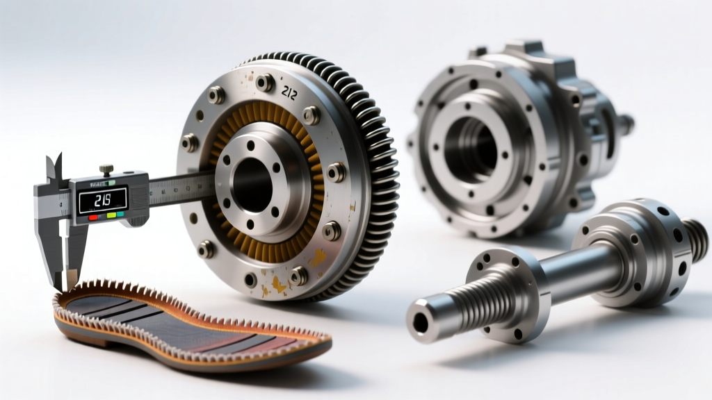
A warped flywheel will cause the clutch disc to bind and drag even when the pressure plate is fully released. When having a dual-mass or single-mass flywheel resurfaced at a machine shop, you must verify the step height. The step height is the distance between the friction surface and the mounting pad of the pressure plate. If the machine shop removes 0.020 inches of material from the friction surface but does not account for the step height, the pressure plate will sit lower. This alters the geometry of the diaphragm spring, reducing clamp load (causing slip) and altering the release point (causing drag).
Diagnostic Data Table: Common Clutch Drag Culprits & 2026 Repair Costs
| Root Cause | Primary Symptom | Diagnostic Test | Estimated 2026 Cost (Parts/Labor) |
|---|---|---|---|
| Air in Hydraulic CSC | Spongy pedal, grinding into 1st/Reverse | Reverse pressure bleed; check slave stroke | $45 (Fluid/Bleed Kit) / $150 Labor |
| Seized Pilot Bearing | Car creeps forward with clutch in; gear clash | Shut off engine, press clutch, shift to 1st (grind stops) | $15 (Bearing) / $600+ (Trans Drop) |
| Warped Clutch Disc | Pulsing pedal, intermittent drag at high RPM | Dial indicator runout test on disc hub | $250-$450 (LuK RepSet) |
| Incorrect Trans Fluid | Hard shifting cold, synchro drag mimicking clutch drag | Check fluid viscosity against OEM spec | $60 (OEM MTF Fluid) |
Step 4: Fluid Viscosity & Synchromesh Compatibility
Before reassembling, it is critical to address a phenomenon that mimics clutch drag: synchromesh drag caused by incorrect transmission fluid. Many DIYers mistakenly fill manual transmissions with thick 75W-90 GL-5 gear oil. GL-5 contains high levels of sulfur-phosphorus extreme pressure additives, which are corrosive to yellow metals (bronze synchro rings) and far too viscous for modern blocker rings.
When the fluid is too thick, the synchro rings cannot cut through the fluid film to grab the gear cone, resulting in a 'drag' sensation and gear crunch that feels exactly like a failing clutch. According to engineering standards published by SAE International, modern manual transmissions require specialized low-viscosity Manual Transmission Fluids (MTF).
- Tremec T56 Magnum / Magnum F: Requires Tremec MTF (Part # TUN 1060000020). Do not substitute with Dexron III or generic synchromesh fluids, as TREMEC explicitly warns this will void the warranty and cause shift rail binding.
- Honda K-Series / H-Series: Requires OEM Honda MTF (Part # 08798-9031). Using heavy gear oil will cause immediate 2nd-gear grind on cold starts.
- BMW ZF GS6-45BZ: Requires specific BMW MTF-LT-3 fluid to ensure proper carbon synchro ring engagement.
Final Reassembly Protocol and Torque Specifications
When reinstalling the clutch assembly to resolve your drag and release problems, precision is mandatory. Use a dedicated clutch alignment tool that matches the exact spline count and pilot diameter of your input shaft (e.g., 26-spline for T56 Magnum, 10-spline for older Ford T5s). An aligned disc prevents the transmission bell housing from binding on the dowel pins, which can crack the aluminum casing.
Follow the OEM torque sequence for the pressure plate bolts, tightening in a star pattern in 5 lb-ft increments to prevent warping the diaphragm spring housing. For example, on a GM LS flywheel, the pressure plate bolts are typically torqued to 22-26 lb-ft, while the flywheel to crankshaft bolts require 74 lb-ft plus an additional 90 degrees of rotation (TTY). Finally, ensure the transmission is fully seated against the engine block before tightening the bell housing bolts; using the bolts to 'winch' the transmission into place will misalign the input shaft, instantly destroying the pilot bearing and causing the exact clutch drag issues you just spent hours diagnosing.