The Hidden Drivetrain Mimic: Why Fan Clutch Diagnostics Matter
When a driver complains of sluggish acceleration, high-RPM roaring, or a mysterious shudder that feels exactly like a failing Torque Converter Clutch (TCC), the transmission is often blamed. However, as we navigate the automotive landscape in 2026, experienced drivetrain technicians know that a failing engine cooling fan clutch is one of the most common culprits of parasitic drag and NVH (Noise, Vibration, and Harshness). Because the fan clutch is bolted directly to the water pump snout—which is driven by the crankshaft via the serpentine belt—a seized or dragging fan clutch places a massive mechanical load on the engine. This load mimics a slipping manual transmission clutch or a dragging TCC.
To prevent unnecessary transmission teardowns, this technical deep-dive provides a comprehensive clutch system inspection checklist specifically tailored for viscous and electronic engine cooling fan clutches. We will cover shear dynamics, thermal engagement thresholds, and the definitive isolation test.
Anatomy of a Viscous Engine Cooling Fan Clutch
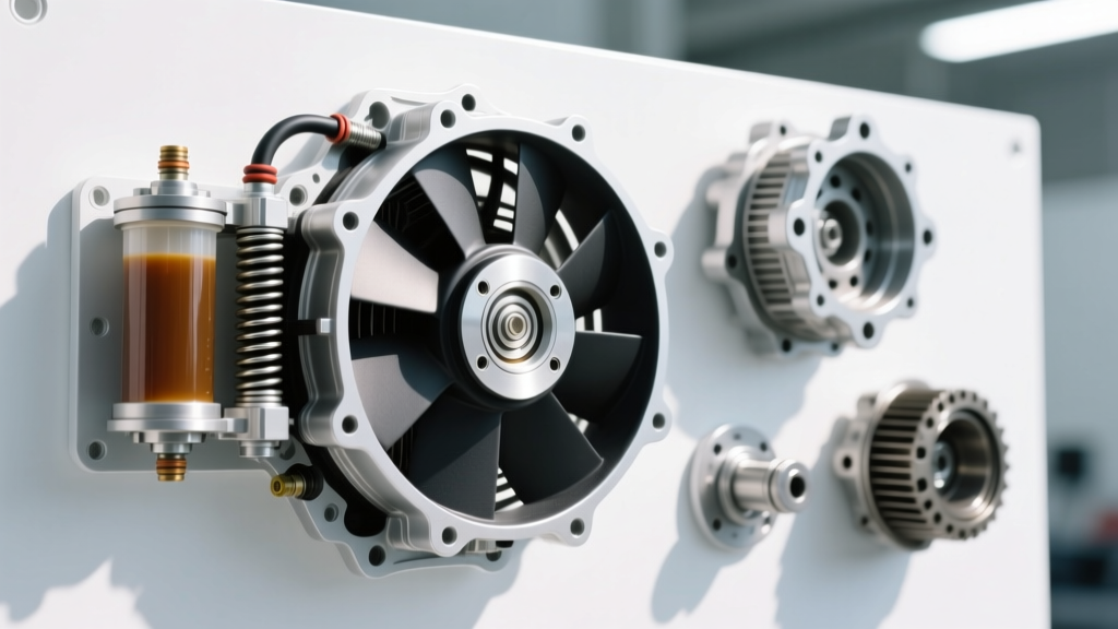
Before executing the inspection checklist, it is critical to understand the internal mechanics. A traditional thermal fan clutch consists of two primary shear plates separated by a precise air gap, a reservoir of high-viscosity silicone fluid, and a bimetallic thermal strip (or wax pellet) mounted on the front face.
- Silicone Fluid Viscosity: Standard-duty clutches typically utilize silicone oil rated around 10,000 centistokes (cSt). Heavy-duty and severe-duty applications (e.g., towing packages) use fluids ranging from 20,000 to 30,000 cSt. Using the wrong replacement viscosity will alter the shear dynamics, leading to either overheating at idle or excessive parasitic drag at highway speeds.
- Thermal Valve Armature: As ambient air passing through the radiator reaches the clutch face, the bimetallic strip expands. This opens the internal valve, allowing silicone fluid to migrate from the reservoir into the shear chamber, locking the input and output plates together via fluid friction.
Diagnostic Rule of Thumb: The thermal spring reacts to air temperature at the radiator face, not engine coolant temperature. A clogged radiator core will block hot air from reaching the clutch face, causing the clutch to remain disengaged even if the engine is overheating.
Essential Tools for the Inspection Checklist
Do not attempt to diagnose or remove a fan clutch without the proper tooling. Prying on the fan blades or using adjustable wrenches on the water pump snout will result in catastrophic damage to the water pump bearings.
- Fan Clutch Wrench Set: OTC 4521 or Lisle 39260 (includes 36mm, 47mm, and 22mm thin-profile wrenches).
- Infrared (IR) Thermometer: For measuring radiator face and bimetallic strip temperatures.
- Scan Tool (Bi-Directional): Required for diagnosing electronic viscous clutches found on GMT900 and later platforms.
- Stethoscope: For isolating bearing noise from internal transmission pump cavitation.
Phase 1: Cold Start & Visual Inspection Checklist
Perform this phase with the engine completely cold (sitting overnight). This establishes the baseline mechanical health of the clutch assembly.
1. The Spin-Down Test
With the engine off, reach behind the fan shroud and spin the fan blade by hand. A healthy viscous clutch will offer moderate resistance. It should spin approximately 1 to 1.5 revolutions and then stop abruptly as the silicone fluid settles into the reservoir.
- Failure Mode A (Free-Spinning): If the fan spins freely like a bicycle wheel with zero resistance, the internal shaft seal has failed, and the silicone fluid has leaked out. The clutch is completely inoperative and will cause severe overheating in traffic.
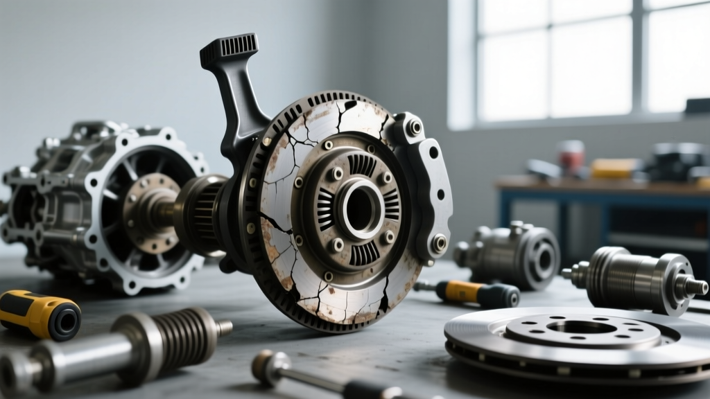
- Failure Mode B (Seized/Solid): If the fan will not budge, or requires extreme force to turn, the internal shear plates have galled together, or the bearing has seized. This is the exact condition that causes highway-speed parasitic drag and mimics a dragging transmission clutch.
2. Visual Seal and Bearing Inspection
Inspect the rear of the clutch hub where the shaft enters the body. Look for a glossy, clear, or slightly milky residue. This is weeping silicone oil. Additionally, grasp the fan blade and attempt to wobble it up and down. Any radial or axial play indicates water pump bearing failure or a worn clutch pilot bearing.
Phase 2: Thermal Engagement & Spin-Down Testing
This phase verifies the calibration of the thermal valve. You will need an assistant and an IR thermometer.
- Start the engine cold. The fan should engage briefly (a 'morning sickness' roar) as the fluid in the shear chamber is distributed, then disengage and quiet down within 60 seconds.
- Allow the engine to reach full operating temperature. Point your IR thermometer at the bimetallic spring on the front face of the clutch.
- As the thermostat opens and hot coolant flows through the radiator, the air temp at the clutch face will rise. Engagement typically occurs between 150°F and 185°F (65°C - 85°C).
- When the clutch engages, you will hear a distinct increase in fan roar, and the IR thermometer will show a rapid spike in air temp as airflow increases.
Fan Clutch Engagement Temperature Specifications
| Clutch Duty Rating | Typical Engagement Temp (Air) | Typical Application | Silicone Viscosity |
|---|---|---|---|
| Standard Duty | 150°F - 165°F | Passenger Cars, Light SUVs | ~10,000 cSt |
| Heavy Duty | 160°F - 175°F | 1/2 Ton Trucks, V8 SUVs | ~20,000 cSt |
| Severe Duty | 170°F - 185°F | 3/4 Ton Trucks, Tow Packages | ~30,000 cSt |
| Electronic Viscous | ECM Controlled (PWM) | GMT900, Modern Diesels | Varies |
Phase 3: Isolating Fan Clutch Noise from Drivetrain Symptoms
This is the most critical step in the clutch system inspection checklist. How do you prove the shudder or drag is the fan clutch and not the transmission's TCC or the manual flywheel clutch?
The Unbolt-and-Isolate Test
If you suspect the fan clutch is causing parasitic drag or low-frequency vibration that the customer attributes to the drivetrain, perform this definitive test:
- Remove the serpentine belt.
- Unbolt the fan clutch assembly from the water pump snout. (Note: On GM LS engines, the water pump snout nut is typically an M22 x 1.5 Left-Hand thread. You must turn it clockwise to loosen. Forcing it counter-clockwise will snap the water pump snout).
- Carefully rest the unbolted fan assembly on the lower fan shroud, ensuring it is clear of the pulleys and belts.
- Reinstall the serpentine belt and start the engine.
- Take the vehicle for a test drive. If the 'TCC shudder', sluggish acceleration, or high-RPM roaring has completely vanished, the transmission is healthy. The engine cooling fan clutch was the sole source of the mechanical load.
Electronic Viscous Clutch Diagnostics (Modern Platforms)
For vehicles equipped with electronic fan clutches (where the ECM controls a solenoid valve inside the clutch hub via a PWM signal), the thermal strip test is obsolete. According to Hayden Automotive Technical Resources, diagnosing these requires a bi-directional scan tool. You must command the fan clutch solenoid from 10% to 90% duty cycle while monitoring engine RPM and coolant temperature. If the ECM commands 90% engagement but the fan remains disengaged, the internal solenoid has failed, or the wiring harness at the water pump has chafed against the bracket—a common failure point on 2007-2014 GM trucks.
Replacement Specs: Torque, Thread Pitch, and Best Practices
When the inspection checklist confirms a failure, proper installation is paramount to prevent immediate recurrence or water pump damage. Refer to AA1Car Cooling Fan Diagnostics for general cooling system best practices, but adhere to these specific drivetrain-adjacent torque specs:
- GM Gen III/IV (LS/LT) V8: M22 x 1.5 Left-Hand Thread. Torque to 15 lb-ft (20 Nm). Use a new nut if the old one shows thread deformation.
- Ford 4.6L / 5.4L Modular V8: Typically 5/8"-11 UNC Right-Hand Thread or M22 x 1.5 RH depending on the exact water pump casting. Torque to 18 lb-ft (24 Nm).
- Dodge 5.7L HEMI: Uses a bolt-on fan bracket to the water pump pulley, not a threaded snout. Torque bracket bolts to 105 in-lbs (12 Nm).
Cost Expectations: As of 2026, a high-quality heavy-duty replacement (e.g., Hayden 2735 or Four Seasons 36964) ranges from $65 to $95. Severe-duty or electronic clutches (e.g., Hayden 2747 or OEM GM electronic units) can range from $120 to $280. Always replace the clutch as a complete assembly; attempting to refill a viscous clutch with aftermarket silicone oil is a temporary fix that rarely restores correct shear dynamics and will lead to warranty comebacks.
Conclusion
The engine cooling fan clutch is a vital component that bridges the cooling system and the engine's rotational mass. By treating it as a legitimate 'clutch system' and applying this rigorous inspection checklist, transmission and drivetrain technicians can confidently rule out accessory drag before authorizing costly transmission removals. Whether dealing with a traditional thermal viscous unit or a modern ECM-controlled solenoid clutch, isolating the parasitic load is the key to accurate diagnostics and lasting repairs. For further reading on accessory drive diagnostics, consult the Gates Technical Resources library.