The Core Mechanics: How a CVT Transmission Actually Works
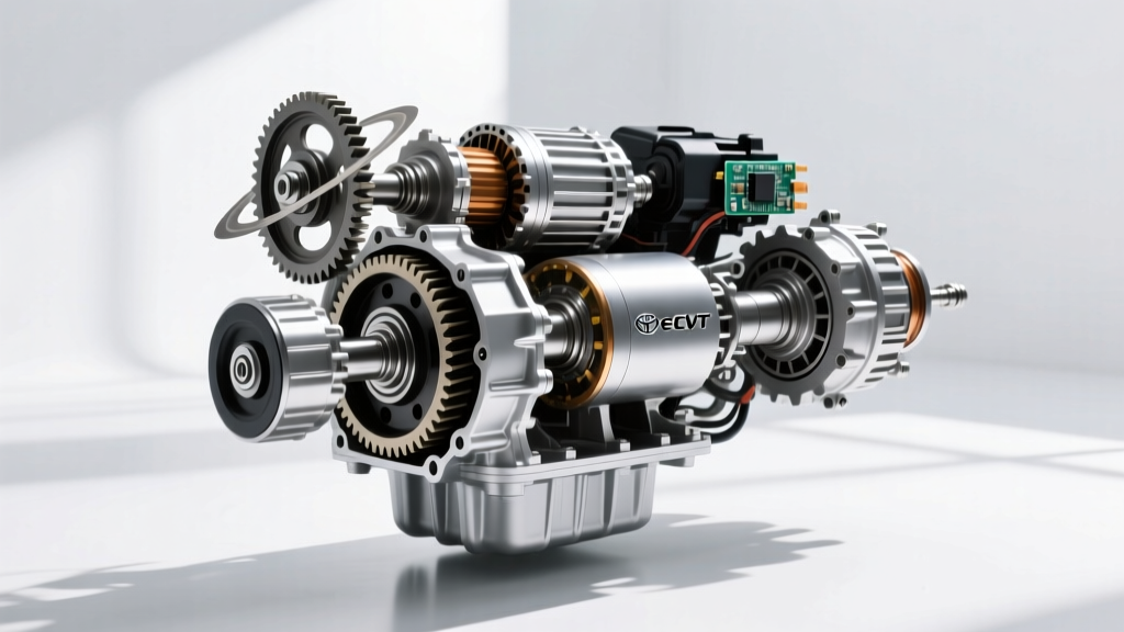
Before you can accurately diagnose and repair a Continuously Variable Transmission (CVT), you must understand its internal operational theory. Unlike traditional planetary automatics (such as the ZF 8HP or GM 6L80) that use fixed gear sets and clutch packs to shift, a CVT relies on a variable-pitch pulley system connected by a steel push-belt or chain. This allows for an infinite number of gear ratios, keeping the engine in its optimal power or efficiency band.
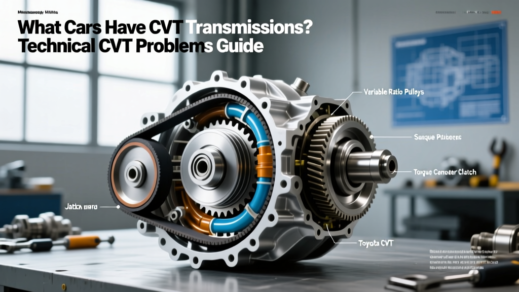
In a typical push-belt CVT, like the widely used Jatco JF011E (found in Nissan and Mitsubishi vehicles), the system utilizes two hydraulically controlled variable-diameter pulleys: the primary (input) and secondary (output) pulleys. Each pulley consists of two conical sheaves. By altering the hydraulic clamping pressure applied to these sheaves, the transmission changes the riding radius of the LuK steel push-belt. The belt itself is a marvel of engineering, comprising hundreds of high-carbon steel elements held together by flexible steel rings. Power is transmitted via compression (pushing) rather than tension (pulling).
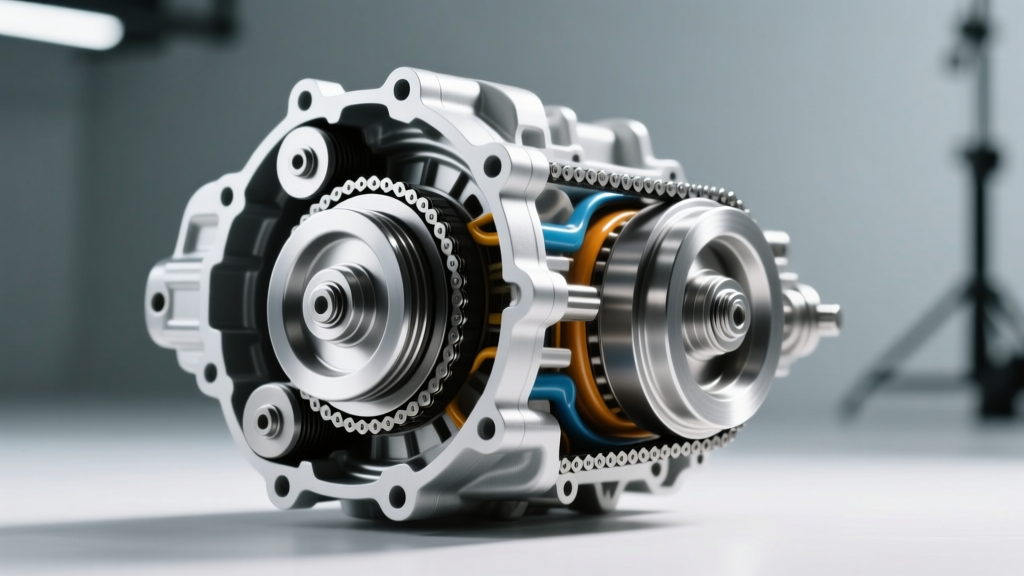
Conversely, chain-driven CVTs, such as the Subaru Lineartronic or the Honda HCF-2, use a Schaeffler chain that operates via tension and features link pins that articulate inside the conical sheaves. Understanding whether your unit uses a belt (compression) or chain (tension) is the foundational step in learning how to fix CVT transmission problems, as the failure modes and hydraulic pressure requirements differ drastically between the two architectures.
Step 1: Electronic & Ratio Diagnostics
The first step in any CVT repair is verifying the electronic control strategy and monitoring the actual gear ratio. Modern CVTs are managed by a dedicated Transmission Control Module (TCM) that constantly calculates the target ratio based on throttle position, vehicle speed, and engine load.
- Monitor Input/Output Speed Sensors: Connect an advanced bi-directional scanner. Calculate the real-time ratio by dividing the primary pulley RPM by the secondary pulley RPM. If the scanner shows a commanded ratio of 2.5:1 but the actual ratio is slipping to 1.8:1 under load, you have a hydraulic clamping pressure failure or severe sheave wear.
- Test the Stepper Motor (JF011E/JF016E): In Jatco units, a stepper motor controls the line pressure to the primary pulley via a control valve. If the vehicle enters limp mode (stuck in a 1:1 ratio), test the stepper motor. Using a multimeter, measure the resistance across the motor pins. The specification is typically 10 to 14 ohms at 20°C (68°F). An open or shorted circuit mandates immediate replacement of the motor and a complete valve body flush.
- Check the Forward/Reverse Clutch Solenoids: Unlike Toyota's K313 CVT which uses a traditional torque converter, Nissan CVTs use a forward/reverse planetary clutch pack and a start clutch. Slipping during initial engagement from a stop usually points to degraded clutch friction material or a failing F/R clutch solenoid, not the pulley belt itself.
Step 2: Hydraulic Line Pressure Verification
Hydraulic pressure is the lifeblood of a CVT. If clamping pressure drops even slightly, the belt will slip against the sheaves, causing microscopic scoring that rapidly destroys the transmission. To fix CVT transmission problems related to slipping or shuddering, you must perform a manual line pressure test.
- Locate the primary and secondary pressure test ports on the transmission case.
- Connect a calibrated 0-1000 PSI hydraulic gauge.
- Perform a stall test (brake applied, throttle to 2000 RPM max for no more than 5 seconds).
- Target Pressures: For a Jatco JF011E, primary line pressure should spike to approximately 550 - 600 PSI during stall, while secondary pressure should read around 150 - 200 PSI. If pressures are low, the issue is rarely the main pump; it is almost always a worn pressure regulator bore in the valve body.
Expert Tip: As of 2026, aftermarket solutions like the Sonnax Zip Kits are the industry standard for repairing worn valve body bores. Replacing the entire valve body is often unnecessary if you ream the bore and install a sleeved pressure regulator valve.
Step 3: Mechanical Teardown & Measurement
If electronic and hydraulic tests confirm internal mechanical failure, the unit must be removed and torn down. When disassembling the variator assembly, precision measurement is critical.
Inspecting the Pulley Sheaves
Use a straight edge and feeler gauge to check the sheave faces for scoring. Even a 0.05mm groove in the hardened steel sheave will cause the belt to chatter and shudder at highway speeds. If the sheaves are damaged, the variator assembly must be replaced as a matched set; you cannot mix primary and secondary pulleys from different cores due to microscopic calibration differences.
Measuring the Push-Belt
Inspect the steel elements of the LuK belt. Look for edge wear, galling, or fractured rings. A single fractured ring will eventually snap under load, sending shrapnel through the transmission case. If the belt shows any signs of polishing or edge wear, it must be replaced. Never reuse a CVT belt.
CVT Component Failure Modes & Repair Matrix
The following table outlines specific failure modes based on the internal mechanics of popular CVT platforms, guiding your repair strategy.
| CVT Model | Starting Device | Drive Medium | OEM Fluid Spec | Common Failure Point |
|---|---|---|---|---|
| Jatco JF011E | F/R Clutch Pack | LuK Push Belt | Nissan NS-2 / NS-3 | Stepper Motor & Valve Body Bore |
| Toyota K313 | Torque Converter | LuK Push Belt | Toyota CVTF-FE | Secondary Pressure Sensor & Pump |
| Honda HCF-2 | Start Clutch | Chain Drive | Honda HCF-2 | Start Clutch Burn-up & Chain Stretch |
| Subaru Lineartronic | Torque Converter | LuK Chain | Subaru CVTF-II | Chain Guide Wear & Solenoid Screen |
Step 4: Reassembly, Fluid Selection, and Adaptive Relearning
Rebuilding a CVT requires strict adherence to torque specifications and fluid chemistry. Using the wrong fluid is the fastest way to destroy a newly rebuilt CVT. The friction modifiers in Nissan NS-3 are specifically engineered for the clamping pressure and friction coefficient of steel-on-steel push belts, whereas Honda HCF-2 fluid is formulated for chain tension and start-clutch engagement. Never cross-reference these fluids.
Critical Torque Specs & Clearances
- Torque Converter to Flex Plate: 33 ft-lbs (45 Nm). Always use new, grade 10.9 bolts and apply medium threadlocker.
- Bellhousing to Engine Block (e.g., Nissan QR25DE): 35 ft-lbs (47 Nm).
- Primary/Secondary Pulley Shaft Nuts: These are often torque-to-yield. Consult the specific OEM service manual for the exact torque + angle specification (e.g., 40 ft-lbs + 90 degrees).
The Relearn Procedure
Once reassembled and filled with the exact fluid capacity (typically 4.5 to 5.0 quarts for a JF011E drain-and-fill), the repair is not complete. You must perform a TCM adaptive learning procedure. This involves bringing the transmission fluid to exactly 104°F - 113°F (40°C - 45°C), clearing old adaptation data via the scanner, and driving the vehicle through a specific sequence of light, medium, and heavy throttle accelerations. This allows the TCM to re-map the solenoid duty cycles to the new mechanical clearances of the rebuilt valve body and pulleys.
Final Thoughts on CVT Longevity
Understanding how a CVT transmission works demystifies the repair process. The vast majority of CVT failures are not caused by the belt snapping out of nowhere; they are the result of neglected fluid degradation, clogged internal suction screens, or worn valve body bores leading to insufficient clamping pressure. By following this step-by-step diagnostic framework, referencing ATRA technical bulletins, and utilizing precision measurement tools, you can reliably diagnose and fix CVT transmission problems, restoring the seamless, infinite-ratio driving experience these units were designed to deliver.