When you discover your clutch master cylinder leaking fluid down the firewall or onto your pedals, the immediate fix is a replacement. However, simply swapping in an identical OEM unit is a missed opportunity. Whether you are restoring a classic, performing an LS swap, or building a dedicated track car, replacing a failed master cylinder is the perfect time to evaluate and optimize your clutch master cylinder bore size. In modern 2026 restomod and EV-conversion builds, correct hydraulic geometry is critical for achieving a modern, linear pedal feel.
Diagnosing the Clutch Master Cylinder Leaking
Before tearing into the hydraulic system, confirm the exact failure point. Master cylinders typically fail in one of two ways:
- External Seal Failure (Pushrod Seal): Fluid leaks from the rear of the cylinder, pooling on the firewall, pedal assembly, or interior carpet. This is usually caused by a worn rear lip seal or a scored bore from misaligned pedal pushrods.
- Internal Cup Seal Failure (Bypassing): No external fluid is visible, but the clutch pedal slowly sinks to the floor when held down at a red light. The internal piston seals are allowing fluid to bypass back into the reservoir.
If your reservoir is empty but the slave cylinder and hard lines are dry, the master cylinder is undeniably the culprit. Once confirmed, you must determine the correct bore size for your replacement before unbolting the failing unit.
The Physics: Why Bore Size Dictates Pedal Feel
The bore size of your master cylinder determines the volume of fluid displaced per inch of pedal travel. This directly impacts your hydraulic ratio. According to principles outlined by Wilwood Engineering, a smaller bore moves less fluid, requiring more pedal travel but generating higher hydraulic pressure with less foot effort. Conversely, a larger bore moves more fluid, reducing pedal travel but requiring significantly more leg effort to disengage the clutch.
Expert Insight: Upgrading to a heavy-duty twin-disc clutch (like a McLeod RST or Centerforce DYAD) often introduces a stiff pedal. Many enthusiasts mistakenly blame the pressure plate, when the real issue is an undersized 5/8-inch master cylinder struggling to generate the necessary hydraulic volume to fully stroke a large slave cylinder.
Step 1: Calculate Your Required Hydraulic Ratio
To select the correct bore size, you must match the master cylinder's displacement to your slave cylinder's volume and your pedal assembly's mechanical ratio. The formula for total hydraulic system ratio is:
Total Ratio = (Slave Bore Area ÷ Master Bore Area) × Pedal Mechanical Ratio
Most street applications target a total system ratio between 6:1 and 8:1 for optimal modulation. Below is a reference chart for common master cylinder bore sizes and their fluid displacement characteristics.
| Bore Size (Inches) | Bore Area (Sq. In.) | Volume per 1" Travel (Oz) | Best Application | Pedal Effort |
|---|---|---|---|---|
| 5/8" (0.625) | 0.307 | 0.307 | Light single-disc, OEM Honda/Ford, long-travel slaves | Very Light |
| 3/4" (0.750) | 0.442 | 0.442 | Standard V8 swaps, T56 Magnum, Tremec TKO, LS conversions | Moderate / OEM |
| 13/16" (0.8125) | 0.518 | 0.518 | Heavy-duty trucks, twin-disc street clutches, short-throw slaves | Firm |
| 7/8" (0.875) | 0.601 | 0.601 | Dedicated track cars, aggressive ceramic/metallic pucks | Very Heavy |
Step 2: Sourcing the Correct Replacement Cylinder
Once you have identified the target bore size (typically 3/4" for 80% of V8 swap applications), source a high-quality replacement. Avoid cheap, unbranded cast-iron units from overseas marketplaces; their bores are often poorly honed, leading to premature seal wear and recurring leaks.
Recommended Performance Options
- Wilwood 3/4" Compact Master (Part #260-1304): Priced around $135. Features a hard-anodized aluminum bore and high-temp internal seals. Ideal for tight firewall clearances in S10 and Nova swaps.
- Tilton 7/8" Racing Master (78-Series): Priced around $240. The gold standard for road racing where heavy metallic clutches require massive fluid displacement and zero pedal flex.
- OEM GM LS Truck Master (Part #14065051): A reliable 3/4" plastic/composite unit available for roughly $65-$85. Excellent for budget-friendly, stock-feel LS swaps.
Step 3: Removal and Bench Bleeding
Removing a leaking master cylinder requires care to avoid damaging the firewall or stripping aged hardware.
- Extract Fluid: Use a turkey baster or fluid evacuator to empty the reservoir. This prevents DOT fluid from eating your paint when the lines are disconnected.
- Disconnect Hard Line: Use a 7/16" or 1/2" line wrench (flare nut wrench) on the output fitting. Never use an open-end wrench, as you will round off the soft brass or steel fitting nut.
- Unbolt from Firewall: Remove the two mounting nuts (typically 13mm or 1/2") inside the cabin or on the engine side, depending on the vehicle.
The Bench Bleeding Protocol
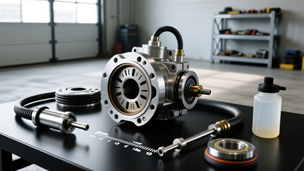
Before installation, you must bench bleed the new master cylinder. Installing a dry master cylinder will trap air in the primary and secondary cup seals, making the system nearly impossible to bleed via the slave cylinder.
- Mount the cylinder in a vise (use soft jaws to protect the aluminum body).
- Fill the reservoir with fresh DOT 3 or DOT 4 fluid.
- Attach a clear rubber hose to the output port and route the other end back into the reservoir, submerged in fluid.
- Use a blunt punch to slowly stroke the pushrod in and out. Watch the clear hose; once bubbles cease and only solid fluid flows, the cylinder is bench-bled.
Step 4: Installation and Torque Specifications
Proper installation prevents the very issue you are trying to fix. A misaligned master cylinder will cause the pushrod to ride at an angle, scoring the bore and destroying the rear seal within 500 miles.
- Firewall Flex: If your firewall is thin or unbraced, the firewall will flex backward when you press the clutch, absorbing pedal travel. Install a firewall reinforcement plate (e.g., from ICT Billet or Holley, ~$45) to ensure all hydraulic pressure translates to the slave cylinder.
- Pushrod Clearance: There must be a slight amount of free-play (typically 0.010" to 0.020") between the pedal pushrod and the master cylinder piston. If the pushrod is pre-loaded, it will block the internal compensation port, causing the clutch to drag and the fluid to overheat and boil.
Crucial Torque Specs
Referencing data from Tilton Racing's technical documentation and standard SAE fastener guidelines, adhere to the following torque specifications:
- Firewall Mounting Nuts (M8 / 5/16"): 15 - 18 lb-ft (20 - 24 Nm). Do not overtighten, or you will crush the plastic reservoir housing or warp the aluminum mounting flange.
- Flare Nut Line Fitting: 11 - 14 lb-ft. Use a torque wrench; overtightening will split the brass flare seat.
- Banjo Bolt (if applicable): 18 - 22 lb-ft. Always use two new copper or aluminum crush washers.
Step 5: Advanced Reverse Bleeding Techniques
Traditional gravity bleeding or pump-and-hold methods often leave microscopic air bubbles trapped in the high points of the hard lines or inside the slave cylinder bore. For a firm, leak-free, and responsive pedal, reverse bleeding is the industry standard for modern hydraulic clutch systems.
As noted in Summit Racing's technical guides, pushing fluid from the bottom up forces air out through the path of least resistance—straight up into the master cylinder reservoir.
Reverse Bleeding Step-by-Step
- Attach a large (60cc or larger) medical syringe filled with fresh DOT 4 fluid to a clear hose that fits snugly over the slave cylinder's bleeder nipple.
- Open the bleeder screw on the slave cylinder exactly 1/2 turn.
- Slowly and steadily inject the fluid from the syringe upward through the system. Watch the master cylinder reservoir; you will see air bubbles violently escape to the surface.
- Keep injecting until the fluid in the reservoir rises to the 'MAX' line and no more bubbles appear.
- Close the bleeder screw before removing the syringe to prevent siphoning air back into the slave.
- Top off the reservoir, secure the cap, and test the pedal. It should feel as firm as a brake pedal with zero sponginess.
Final System Verification
After resolving your clutch master cylinder leaking issue and optimizing the bore size, perform a static clearance check. With the clutch pedal fully depressed, verify that the throwout bearing is not pre-loaded against the pressure plate fingers (for manual transmissions) or that the slave cylinder is not bottoming out internally (for hydraulic concentric slaves). Proper bore sizing not only stops leaks but transforms the driving dynamics of your vehicle, delivering precise, confidence-inspiring shifts every time you row the gears.