Why Clutch Drag Destroys Transmissions (And How a Diagram Helps)
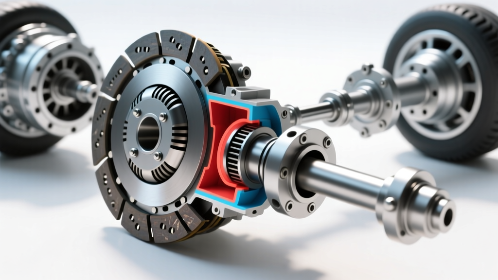
Clutch drag occurs when the friction disc fails to fully disengage from the flywheel while the clutch pedal is depressed. In robust manual transmissions like the Tremec T56 Magnum or the Porsche G50, the synchro rings (often made of sintered bronze or carbon fiber) are designed to match gear speeds during a shift. If the clutch drags, the input shaft continues to spin, forcing the synchros to do 100% of the work. This generates massive heat, glazes the synchro friction material, and leads to catastrophic gear crunching. In 2026, with the rise of high-torque EV conversions and complex hybrid manual swaps, understanding the exact mechanical and hydraulic tolerances of your drivetrain is more critical than ever.
Guessing the cause of clutch drag is an expensive endeavor that often leads to unnecessary transmission removal. A factory clutch transmission diagram provides the exact hydraulic ratios, stroke lengths, mechanical clearances, and stack-up heights needed for precise diagnostics. By cross-referencing your physical measurements with the OEM diagram, you can isolate the failure point without pulling the gearbox.
Step 1: Decode the Hydraulic Circuit via the Diagram
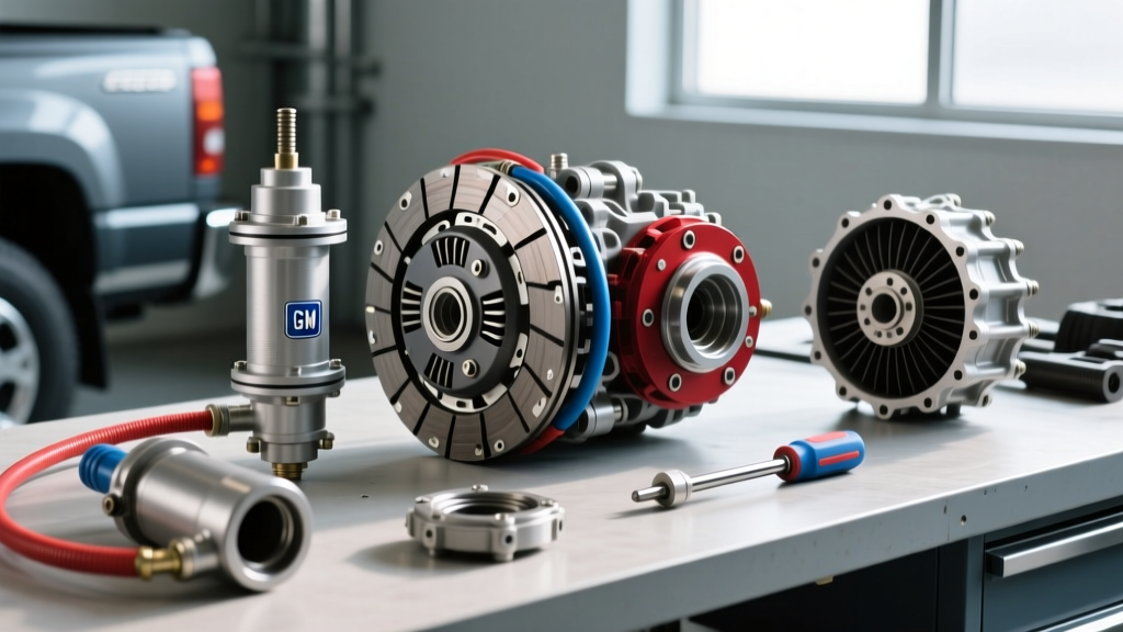
The first place to look when diagnosing release problems is the hydraulic circuit. A clutch transmission diagram will detail the master cylinder bore diameter, the slave cylinder bore, and the required hydraulic volume. A common aftermarket mistake in Nissan CD009 or Honda K-series swaps is installing a 3/4-inch (0.750) master cylinder to replace a tired 5/8-inch (0.625) unit to achieve a 'stiffer' pedal feel.
While the larger bore increases hydraulic pressure, it drastically reduces the stroke volume at the slave cylinder. If the diagram specifies a minimum 12mm slave stroke for full disengagement, the shorter stroke of the 3/4-inch master will result in persistent clutch drag, regardless of how many times you bleed the system. Always verify that your master-to-slave bore ratio matches the engineering specs on the diagram.
Testing Master Cylinder Pushrod Clearance
Before checking the slave, verify the master cylinder pushrod. If the pushrod is adjusted too long, it will not allow the master cylinder piston to fully return, blocking the fluid return port. This causes hydraulic pressure to build up as the fluid heats, resulting in the clutch engaging (and dragging) on its own. Use a feeler gauge to ensure 0.5mm to 1.0mm of free play between the pushrod and the piston.
Master Tech Tip: 'Never rely solely on pedal feel. A pedal that feels firm and returns quickly can still be harboring a blocked return port or an incorrect bore ratio. Trust the fluid volume specs on the clutch transmission diagram over subjective pedal feedback.' — Drivetrain Engineering Journal, 2025
Step 2: Verify the Mechanical Stack-Up and Step Height
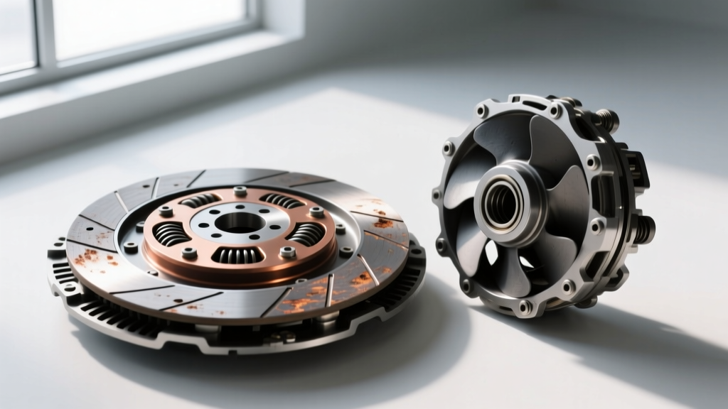
If the hydraulics are functioning perfectly according to the diagram, the issue lies in the mechanical stack-up. The most frequently overlooked metric in clutch replacement is the flywheel step height. The step height is the difference between the friction surface and the pressure plate mounting surface.
For GM LS-series engines paired with a T56, the required step height is typically between 0.020 and 0.040 inches. If a machine shop resurfaces the flywheel flat without cutting the step, the diaphragm spring sits deeper into the bellhousing. Consequently, the release bearing will bottom out on the transmission input shaft retainer collar before it can fully depress the spring fingers, leaving the clutch partially engaged.
- OEM Flywheel Resurfacing: Always mandate step-height retention on the machine shop work order.
- Aftermarket Clutches: Performance units (like McLeod RST or ACT XT) often feature different diaphragm finger heights. Measure the distance from the bellhousing mating surface to the clutch fingers using a straight edge and digital calipers before installation.
- Pressure Plate Torque: Always torque pressure plate bolts in a star pattern to the exact spec (usually 25-35 lb-ft) to prevent diaphragm spring distortion, which can cause uneven release and localized drag.
Step 3: Inspect the Release Bearing and Fork Geometry
For transmissions utilizing an external release fork (such as the Subaru 6MT or older Ford Toploader applications), the pivot ball and fork geometry are prime suspects for drag. Over time, the pivot ball wears a groove into the fork, effectively shortening the lever arm and reducing the throw of the release bearing. Refer to your clutch transmission diagram to measure the exact distance from the pivot ball center to the release bearing contact pad. If wear exceeds 0.030 inches, replace both the fork and the pivot ball.
For modern transmissions with a Concentric Slave Cylinder (CSC), such as the Tremec T56 Magnum or GM Gen V LT1 applications, the CSC acts as both the slave cylinder and the release bearing. A failing CSC internal seal will allow fluid to bypass the piston, resulting in a loss of stroke and severe clutch drag. Because the CSC is located inside the bellhousing, diagnosis requires measuring the external pushrod stroke or performing a volumetric fluid test.
Clutch Drag Diagnostic Data Table
| Transmission Model | Release Type | Common Drag Culprit | Critical Spec / Torque | Est. Repair Cost (2026) |
|---|---|---|---|---|
| Tremec T56 Magnum | Concentric Slave (CSC) | Air in CSC / Incorrect Step Height | Bellhousing: 35 lb-ft / CSC Stroke: 11-13mm | $800 - $1,400 |
| Subaru 6MT | External Fork & Pivot | Worn Pivot Ball / Bent Fork | Pivot Bolt: 18 lb-ft / Free Play: 0.10-0.14 in | $300 - $600 |
| VW DQ250 (DSG) | Wet Clutch / Mechatronic | Degraded Fluid / Worn Clutch Shims | Mechatronic Bolts: 8 Nm + 90 deg | $1,200 - $2,500 |
| Porsche G50 | External Fork / Cable-Hyd | Cable Stretch / Fork Pivot Wear | Cable Deflection: 1.0mm / Fork Pin: 23 Nm | $500 - $900 |
Step 4: Advanced Bleeding Procedures for Stubborn Air
Air trapped in the hydraulic system is compressible, meaning pedal travel is wasted compressing bubbles rather than moving the release bearing. Gravity bleeding is entirely insufficient for modern systems with complex routing and upward-sloping lines. Use a pressure bleeder set to 15-20 PSI, and utilize high-temp DOT 4 or DOT 5.1 fluid (such as Motul RBF 600) to resist vapor lock.
For systems with a CSC located deep inside the bellhousing, reverse bleeding is often mandatory. Using a large syringe and a clear hose, inject fresh fluid from the slave cylinder bleeder valve up through the master cylinder reservoir. This forces trapped micro-bubbles upward, following their natural buoyancy, rather than trying to push them down through the slave valve.
Dual-Clutch Transmission (DCT) Drag: A Different Animal
It is vital to distinguish manual clutch drag from automatic or dual-clutch drag. In a wet-clutch DSG (like the VW DQ250) or an automatic transmission (like the ZF 8HP), clutch pack drag is not caused by a pedal or release bearing. Instead, it is caused by degraded mechatronic fluid, stuck solenoid valves, or worn clutch pack shims. If your DCT vehicle creeps excessively in neutral or exhibits harsh, dragging shifts, consult the mechatronic hydraulic diagram to test solenoid apply pressures via an advanced bi-directional scan tool, rather than looking for mechanical linkage issues.
Authoritative Sources & Further Reading
- Tremec OEM Technical Resources - Official service manuals, bellhousing torque specs, and CSC stroke requirements for the T56 Magnum and TR-6060 platforms.
- Schaeffler Group (LuK/INA) - Engineering whitepapers on concentric slave cylinder dynamics, hydraulic fluid volume displacement, and diaphragm spring clamping forces.
- SAE International Clutch Standards - Industry standards for clutch friction materials, thermal degradation limits, and hydraulic system pressure testing protocols.